
Temperature compensation improvements in radar apparatus

a radar and temperature compensation technology, applied in the direction of reradiation, measurement devices, instruments, etc., can solve the problems of unsatisfactory performance and errors in the estimation of the distance of target vehicles

Active Publication Date: 2007-04-24
TRW LIMITED
View PDF23 Cites 7 Cited by
  • Summary
  • Abstract
  • Description
  • Claims
  • Application Information

AI Technical Summary

Benefits of technology

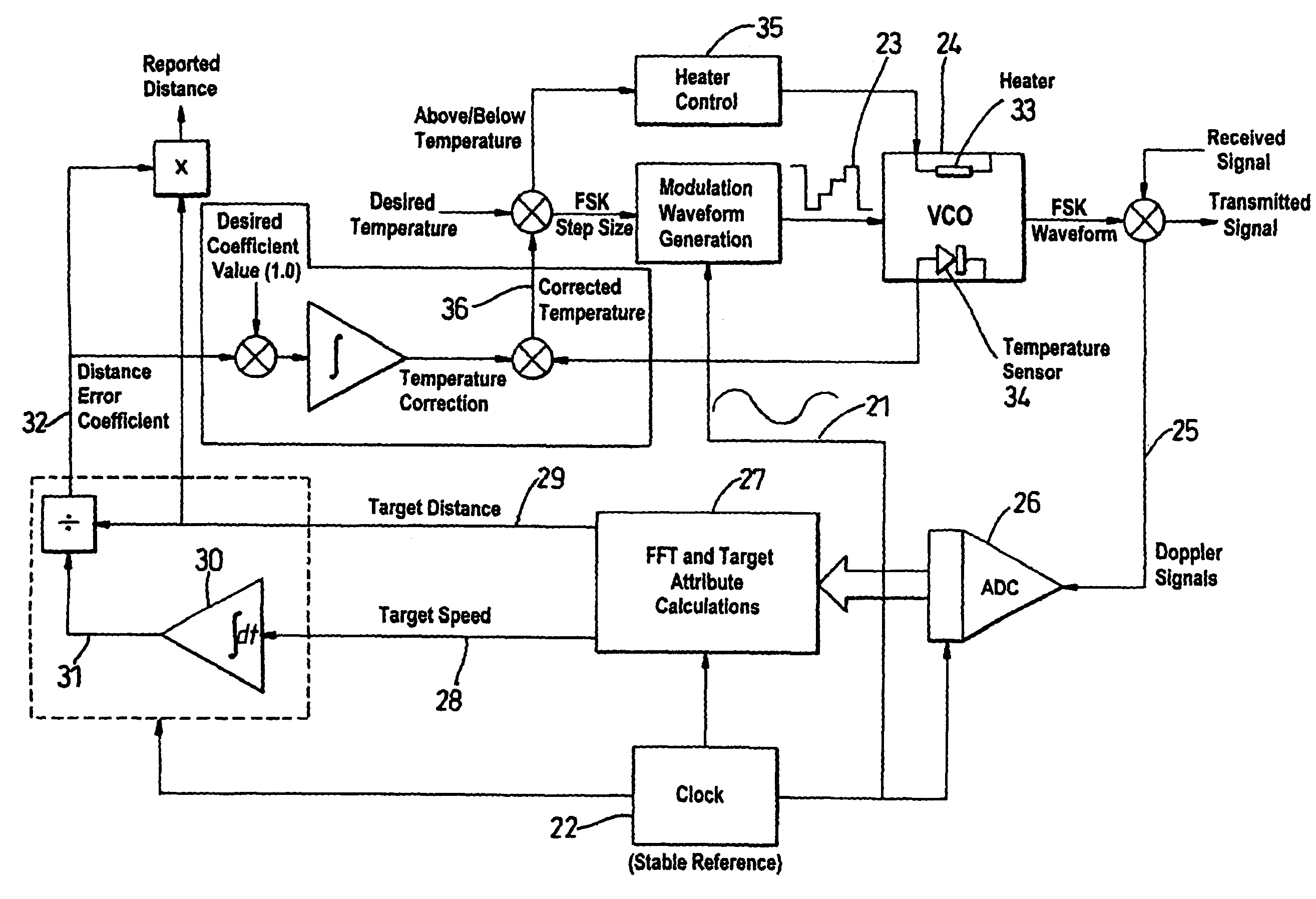
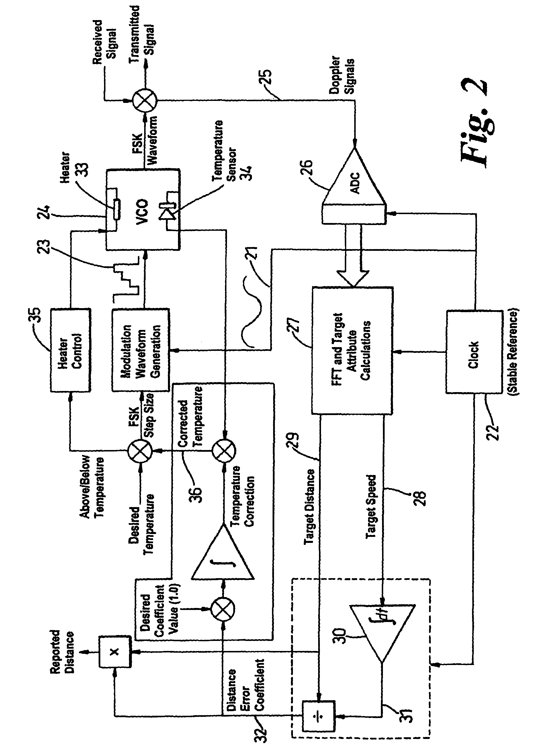
[0016]a frequency regulating means which is adapted to receive the compensated temperature signal and to regulate the frequency of the signal generated by the frequency generator, thereby at least partially correcting for the effect of changes in temperature of the frequency generator.
[0017]Because the compensating means modifies the output of the temperature sensor in a closed loop using information derived from an echo signal, the frequency regulating means can regulate the frequency output by the frequency generator—keeping it as close as possible to an ideal constant value—despite changes in its temperature. Additionally, the compensating means enables the apparatus to correct for the effect of ageing of the temperature sensor or the like. This is not possible in prior art open loop systems in which the output of the temperature sensor is simply assumed to be correct throughout its working life.
[0020]Alternatively, the frequency regulating means may modify the modulating signal applied to the frequency generator according to the value of the compensated temperature signal. For example, if the compensated temperature is at or close to an ideal temperature then no modification of the drive signal may be applied, the amount of modification of the modulating signal increasing as the compensated temperature gets further away from the ideal. Thus, it may alter the size of the frequency steps requested from the frequency generator. This is especially useful if the generator is too hot and above the reference temperature, a condition which cannot be corrected by a heater. In changing the requested step sizes it is possible to cause the generator to produce the correct step sizes in the modulating signal even when temperature causes the frequency generator to work incorrectly.

Problems solved by technology

A problem with such apparatus is that variations in the temperature of the microwave frequency generator cause errors in the estimation of the target vehicles distance.
We have realised that the reliance upon a temperature sensor in a scheme of this type can result in unsatisfactory performance after extended use in harsh environments due to significant ageing effects on the temperature sensor.

Method used


Image

  • Temperature compensation improvements in radar apparatus
  • Temperature compensation improvements in radar apparatus
  • Temperature compensation improvements in radar apparatus

Examples


Embodiment Construction

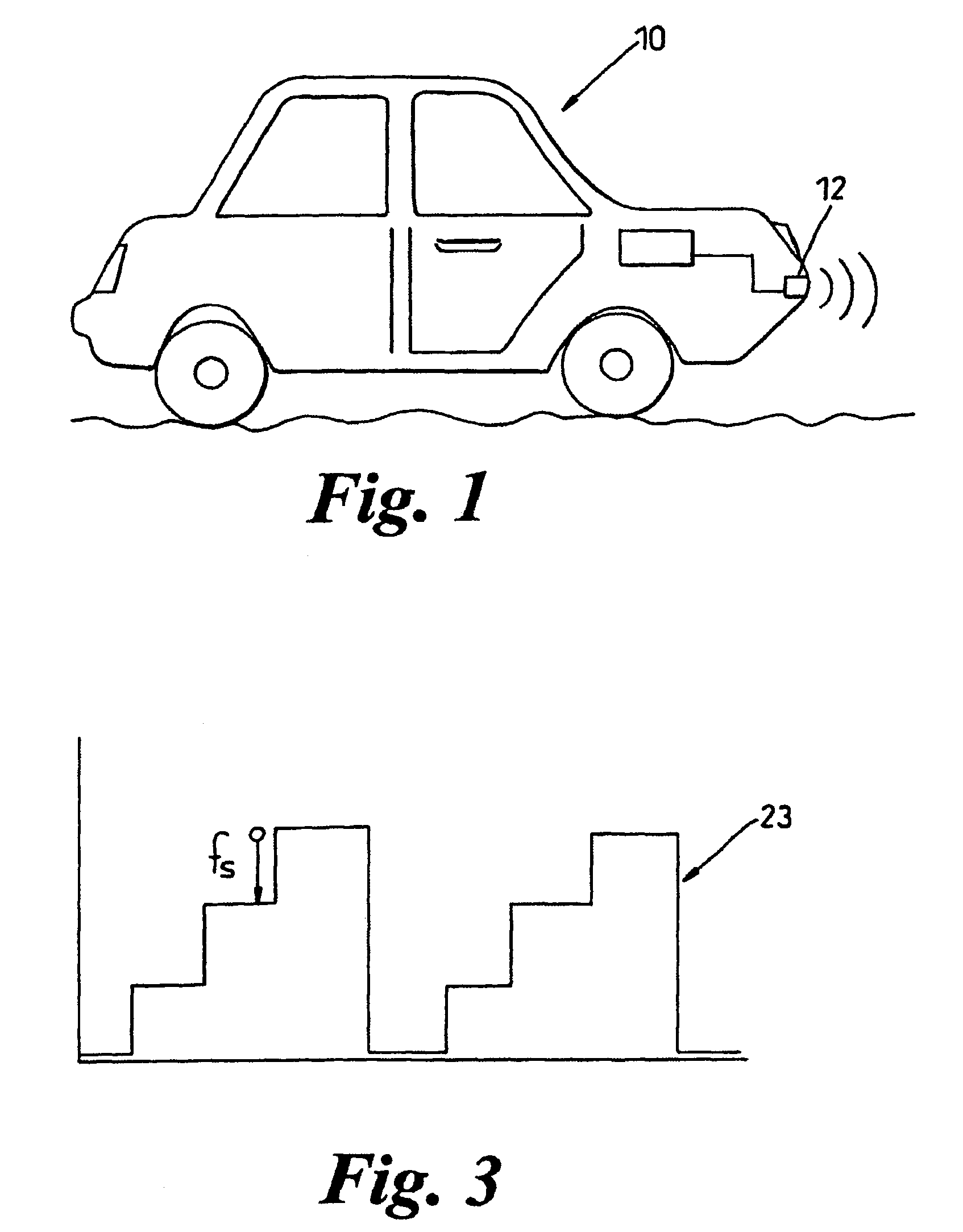
[0037]As shown in FIG. 1, a vehicle 10 is fitted with an example of a radar apparatus in accordance with the present invention. The apparatus comprises a combined microwave source and detector 12. These are mounted towards the front of the vehicle, perhaps at bumper level as shown, where there is a clear and unobstructed (in the microwave range of the spectrum) view ahead of the vehicle as it travels along a road. The source / detector are connected to a processor through a suitable electrical cable.

[0038]As shown in FIG. 2 of the accompanying drawings, the source is driven by a stable voltage controlled oscillator (VCO) 24 which is modulated by a drive signal 23. The drive signal is produced by a modulation voltage waveform generator that is synchronised by a clock 22. The difference in frequency of each of the frequency steps Fs produced by the changing voltage of the drive is known as the FSK step size. A typical drive signal 23, in which four steps are present, is shown in FIG. 3 ...


PUM


Abstract

A radar-based distance measurement apparatus comprises a microwave circuit comprising a frequency generator which produces a microwave frequency signal, the frequency of which is modulated by an amount determined by a modulation signal applied to the frequency generator, a temperature sensor which measures the temperature of at least a part of the microwave circuit, compensating means for processing the output of the temperature sensor to produce a compensated temperature signal using information derived from the drive signal and an echo signal detected by a microwave detector; and a frequency regulating means which is adapted to receive the compensated temperature signal and to regulate the frequency of the signal generated by the frequency generator, thereby at least partially correcting for the effect of changes in temperature of the frequency generator. Because the compensating means modifies the output of the temperature sensor in a closed loop using information derived from an echo signal, the frequency regulating means can regulate the frequency output by the frequency generator—keeping it as close as possible to an ideal constant value—despite changes in its temperature.

Description

CROSS REFERENCE TO RELATED APPLICATIONS[0001]This application is a continuation of International Application No. PCT / GB2003 / 005553 filed Dec. 18, 2003, the disclosures of which are incorporated herein by reference, and which claimed priority to Great Britain Patent Application No. 0229515.2 filed Dec. 19, 2002, the disclosures of which are incorporated herein by reference.BACKGROUND OF THE INVENTION[0002]This invention relates to improvements in radar apparatus using microwave frequency components, and in particular to a radar circuit, which incorporates temperature compensation for microwave components.[0003]It is known to use radar in the measurement of distance. In one application radiation in the microwave region of the spectrum is emitted from a source towards a target. The target will reflect some of this radiation back towards a detector, which is sensitive to radiation in the microwave region of the spectrum. An electronic circuit, which may include a digital signal processo...

Claims


Application Information

Patent Timeline
IPC IPC(8): G01S7/40G01S13/08G01S7/35G01S13/58H03L1/02H03L1/04
CPCG01S7/35G01S7/4008G01S13/584H03L1/022H03L1/04
Inventor TAYLOR, BRIAN KEITH
Owner TRW LIMITED
Learn More