Blade server system

a server system and blade technology, applied in the direction of electrical apparatus construction details, instruments, casings/cabinets/drawers, etc., can solve the problem of increasing rental payments, and achieve the effect of improving system inspection efficiency and reducing manufacturing costs

Active Publication Date: 2007-04-24
QUANTA COMPUTER INC
View PDF2 Cites 20 Cited by
  • Summary
  • Abstract
  • Description
  • Claims
  • Application Information

AI Technical Summary

Benefits of technology

[0007]It is therefore an object of the invention to provide a blade server system, which can selectively inspect the operation status of the server blades and the M / B modules whenever necessary by using a display panel, not only reducing manufacturing costs but also improving the efficiency of system inspection.
[0010]The display panel can slide up and down in the supporting frame for the user to view the display panel conveniently. The display panel includes an adjusting button, wherein the user presses the adjusting button so as to slide the display panel up and down in the supporting frame. The display panel includes a number of buttons for the user to perform basic operations of entering the menu, switching the display items, selecting the display items and exiting the menu. Therefore, with the design of the display panel, the operation status of the server blades and the M / B modules can be inspected whenever necessary, improving inspection efficiency and reducing manufacturing costs.

Problems solved by technology

However, to install a high-efficiency display screen 120 in the rack 110 not only occupies a large space and increases rental payment, but also causes inconveniencies.

Method used


Image

  • Blade server system
  • Blade server system
  • Blade server system

Examples


Embodiment Construction

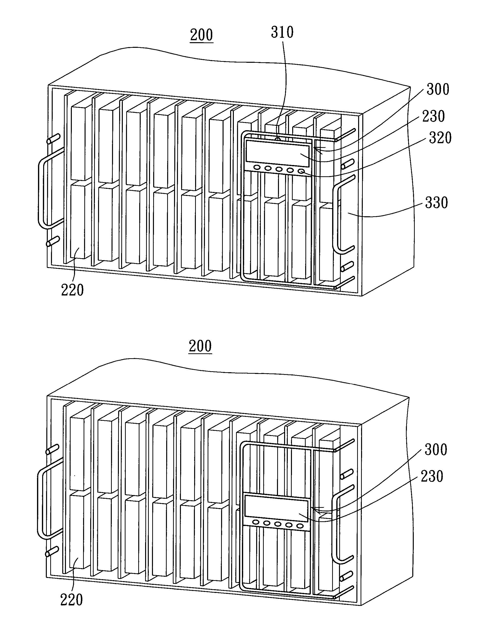
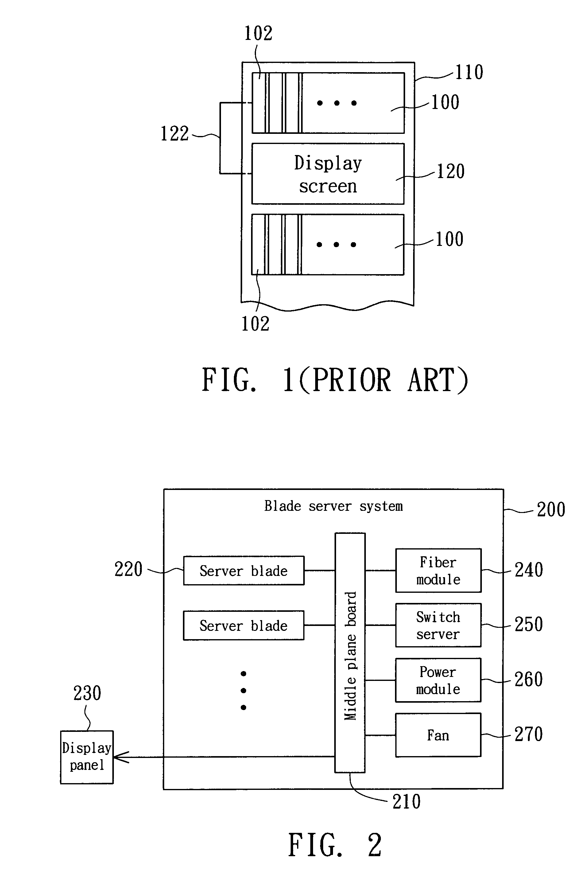
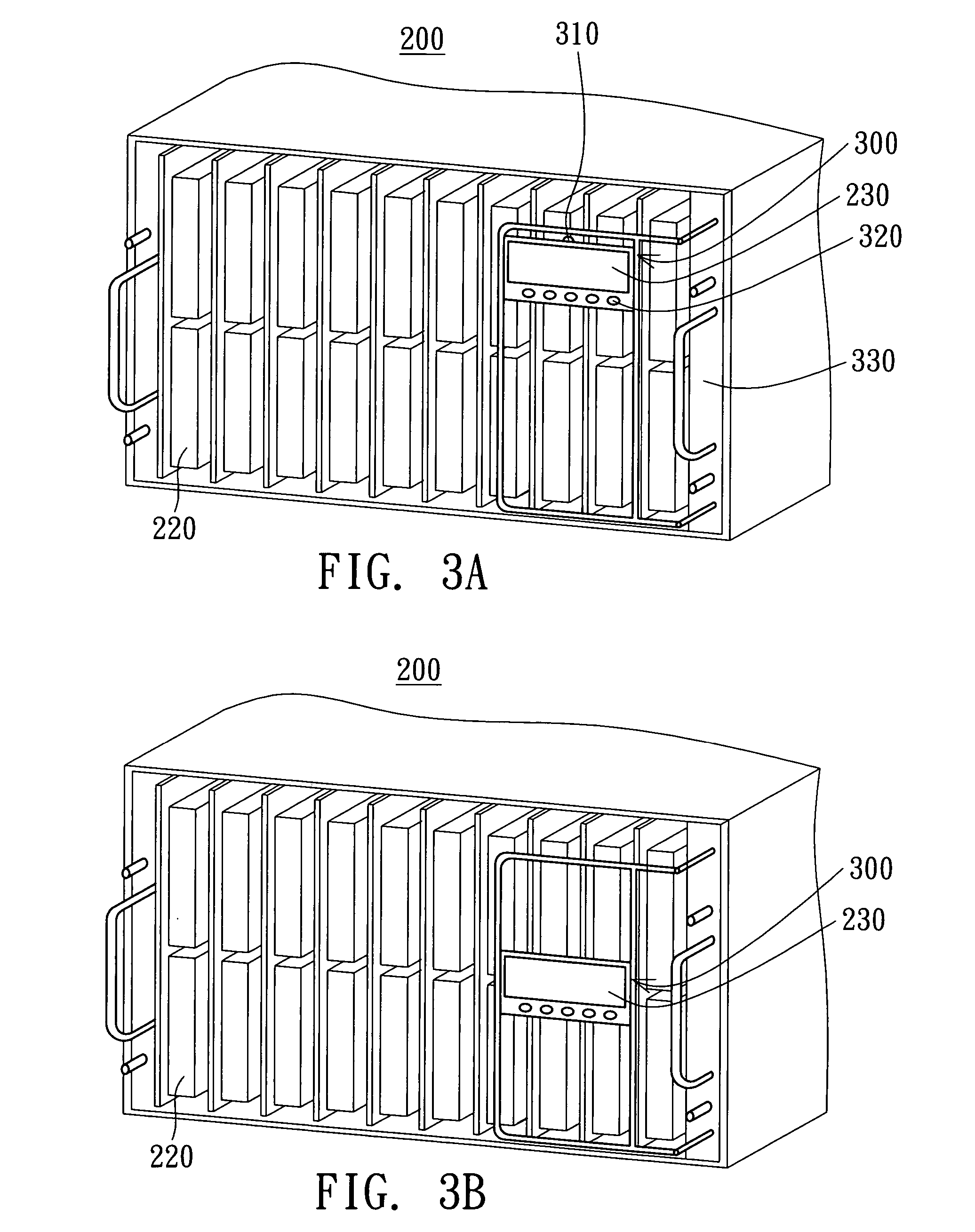
[0018]Referring to FIG. 2, a structural diagram of a blade server system according to a preferred embodiment of the invention is shown. The blade server system 200 includes a middle plane board 210, server blades 220, a display panel 230, a fiber module 240, a switch server 250, a power module 260 and a fan 270, wherein all of the server blade 220, the display panel 230, the fiber module 240, the switch blade 250, the power module 260 and the fan 270 are electrically connected to the middle plane board 210. The fiber module 240 transmits the data processed by the server blade 220, while the switch server 250 performs RJ45 network signal transmission. The display panel 230 can display the operation status of the fiber module 240 and the switch server 250 and the efficiency of data transmission as well as the power supply status of the power module 260 and the operation status of the fan 270. Besides, the display panel 230 can also display the operation status of each server blade 220...


PUM


Abstract

A blade server system including a housing, a middle plane board, a server blade and a display panel is provided. The server blade is electrically connected to the middle plane board, while the display panel is electrically connected to the middle plane board and is slideably disposed on the housing for displaying the operation status of the server blade.

Description

[0001]This application claims the benefit of Taiwan application Serial No. 93120625, filed Jul. 9, 2004, the subject matter of which is incorporated herein by reference.BACKGROUND OF THE INVENTION[0002]1. Field of the Invention[0003]The invention relates in general to a blade server system, and more particularly to a blade server system capable of displaying the operating status of the server blades or the Motherboard (M / B) modules connected to the middle plane.[0004]2. Description of the Related Art[0005]Referring to FIG. 1, a schematic diagram illustrating a conventional blade server system uses a display screen for monitoring and testing is shown. A conventional blade server system 100 is disposed in a rack 110. A display screen 120 is further disposed in the rack 110 to show the operation status of each server blade 102 of the blade server system 100. Normally, a transmission line 122 extends from the display screen 120 to a connector at the rear of each server blade 102 (not sh...

Claims


Application Information

Patent Timeline
Patent Type & Authority Patents(United States)
IPC IPC(8): G06F1/16H05K5/00H05K7/00
CPCG06F1/16H05K7/1494G06F2200/1631
Inventor LIANG, YUAN-CHENLIN, CHENG-WANGLIEN, CHUN-YICHEN, CHAO-JUNG
Owner QUANTA COMPUTER INC
Why Eureka
Try Eureka