Real time power flow method for distribution system

a distribution system and real-time power flow technology, applied in the field of real-time power flow measurement of individual loads, can solve the problems of inability to accurately determine the power flow of the distribution system, the distribution system is not readily available for real-time power flow measurements at individual loads, and the load in the distribution system can be unbalanced

Inactive Publication Date: 2007-04-24
SIEMENS AG
View PDF1 Cites 19 Cited by
  • Summary
  • Abstract
  • Description
  • Claims
  • Application Information

AI Technical Summary

Benefits of technology

[0021]The above described features and advantages, as well as others, may readily be determined by those

Problems solved by technology

While distribution systems are also three phase systems, the loads in distribution systems can be unbalanced due to the presence of two phase and single phase lines and distribution transformers.
However, for several reasons, modeling in distribution systems has typically been limited to non-real time or offline modeling.
In particular, unlike transmission systems, real-time power flow measurements at individual loads are not readily available in distribution systems.
While the usage of power at individual loads is typically metered (i.e. using electricity meters), the metered power information is typically not available in real time.
The lack of real-time power measurement information for the individual loads significantly complicates the development of real-time power flows in distribution systems.
Offline power flows, however, have

Method used


Image

  • Real time power flow method for distribution system
  • Real time power flow method for distribution system
  • Real time power flow method for distribution system

Examples


Embodiment Construction

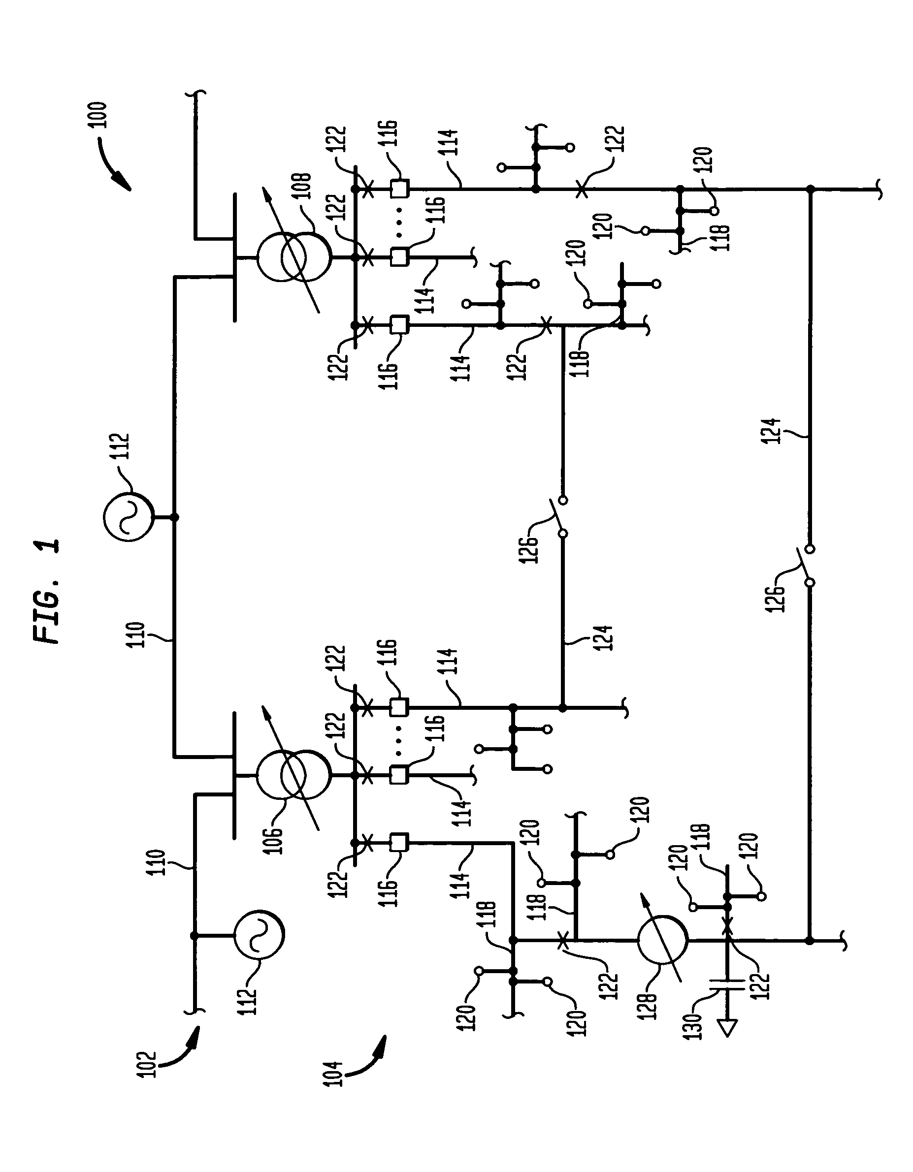
[0029]FIG. 1 shows a schematic representation of a portion of an electrical power network 100 to which aspects of the present invention may be applied. The network 100 includes a transmission network 102, a distribution network 104, and a number of substations in between the transmission network 102 and the distribution network 104. In the portion of the network 100 shown in FIG. 1, two substations 106 and 108 are disposed between the networks 102 and 104.

[0030]The transmission network 102 includes high voltage transmission lines 110 and a number of three phase power generators 112. Each of the first and second substations 106 and 108 connects to the transmission lines 110. The power generators 112 connect to the transmission lines 110 via three phase transformers, not shown; but which are known in the art. It will be appreciated that any number of other power generators and substations, as well as other components, may be connected to the transmission lines 110.

[0031]The distributi...


PUM


Abstract

A method for determining a power flow in a distribution network includes the step of determining an admittance matrix for a circuit that includes a floating transformer in an electrical power distribution system. The admittance matrix includes an admittance of a fictitious shunt connected between a non-grounded winding of the floating transformer and ground. The method also includes the step of obtaining real time power measurements from a portion of the electrical power distribution system including the floating load transformer. The method further includes solving the power flow using the admittance matrix and the real time power measurements.

Description

[0001]This application claims the benefit of U.S. Provisional Patent Application Ser. No. 60 / 434,312, filed Dec. 18, 2002, which is incorporated herein by reference.FIELD OF THE INVENTION[0002]The present invention relates generally to methods of determining power flow, and more particularly, to methods of determining power flow in electrical distribution systems.BACKGROUND OF THE INVENTION[0003]Modeling of the behavior of the electrical power network is of increasing importance in order to ensure reliable electrical service. The electrical power network consists of many interconnected elements, including power generation nodes, transmission systems, distribution systems and loads. Electrical power generators and distribution entities cooperate to achieve delivery of power upon demand. For example, electrical power generation and distribution entities may cooperate to facilitate to transmission of power from Arizona to a high need area in New York City at certain times of day or yea...

Claims


Application Information

Patent Timeline
IPC IPC(8): G06F19/00G01R21/00G06F17/50H02J3/00H02J3/06
CPCH02J3/06H02J2003/007Y04S40/22Y02E60/76H02J2203/20Y02E60/00Y04S40/20
Inventor ROYTELMAN, ILYA
Owner SIEMENS AG
Why Eureka
Try Eureka