Support element

a support element and support tube technology, applied in the direction of combustion air/fuel air treatment, fuel injection apparatus, charge feed system, etc., can solve the problems of increased radial expansion of the fuel injector, increased space requirements in the installation, and warping

Inactive Publication Date: 2007-05-01
ROBERT BOSCH GMBH
View PDF18 Cites 20 Cited by
  • Summary
  • Abstract
  • Description
  • Claims
  • Application Information

AI Technical Summary

Benefits of technology

[0004]By contrast, the support element according to the present invention for a fuel injector has the advantage that the support element on account of its form as well as on account of appropriately designed clips provides for a transfer of the holding-down force of the fuel distribution line on the fuel injector that compensates for tolerances and offsets. To this end, the clips and the clasp of the support element are designed to be axially and radially deformable such that a more uniform distribution of force and thereby a high stability and a robustness in continuous operation are ensured while keeping manufacture and installation simple.
[0005]It is particularly advantageous that the support element is easy to manufacture by stamping from sheet metal.
[0006]Screws or clamping claws for mounting the fuel injector on the front face of the cylinder head are advantageously dispensed with in the support element according to the present invention. Punched out recesses, which are easy to produce, advantageously provide secure fixing of the support element at the fuel injector and simple bracing of the fuel distribution line. The clips are connected by a crosspiece to the clasp of the support element. In another advantageous specific embodiment, the clips are connected to each other by an arch.
[0008]The clasp is also radially and axially flexible, which allows it to compensate for offsets in any direction.

Problems solved by technology

Particularly disadvantageous in the mounting device known from German Published Patent Application No. 29 26 490 is the warping effect of the various mounting elements on the fuel injector.
The flux of force generated in the fuel injector results in deformations and thus to lift changes of the valve needle and even to jamming as well as a compressive and bending load on the housing components, which usually have thin walls and are welded to one another at several points.
Furthermore, any mounting measure, for example by a contact flange, leads to an increase in the radial expansion of the fuel injector and thus to higher space requirements in the installation.

Method used


Image

  • Support element
  • Support element
  • Support element

Examples


Embodiment Construction

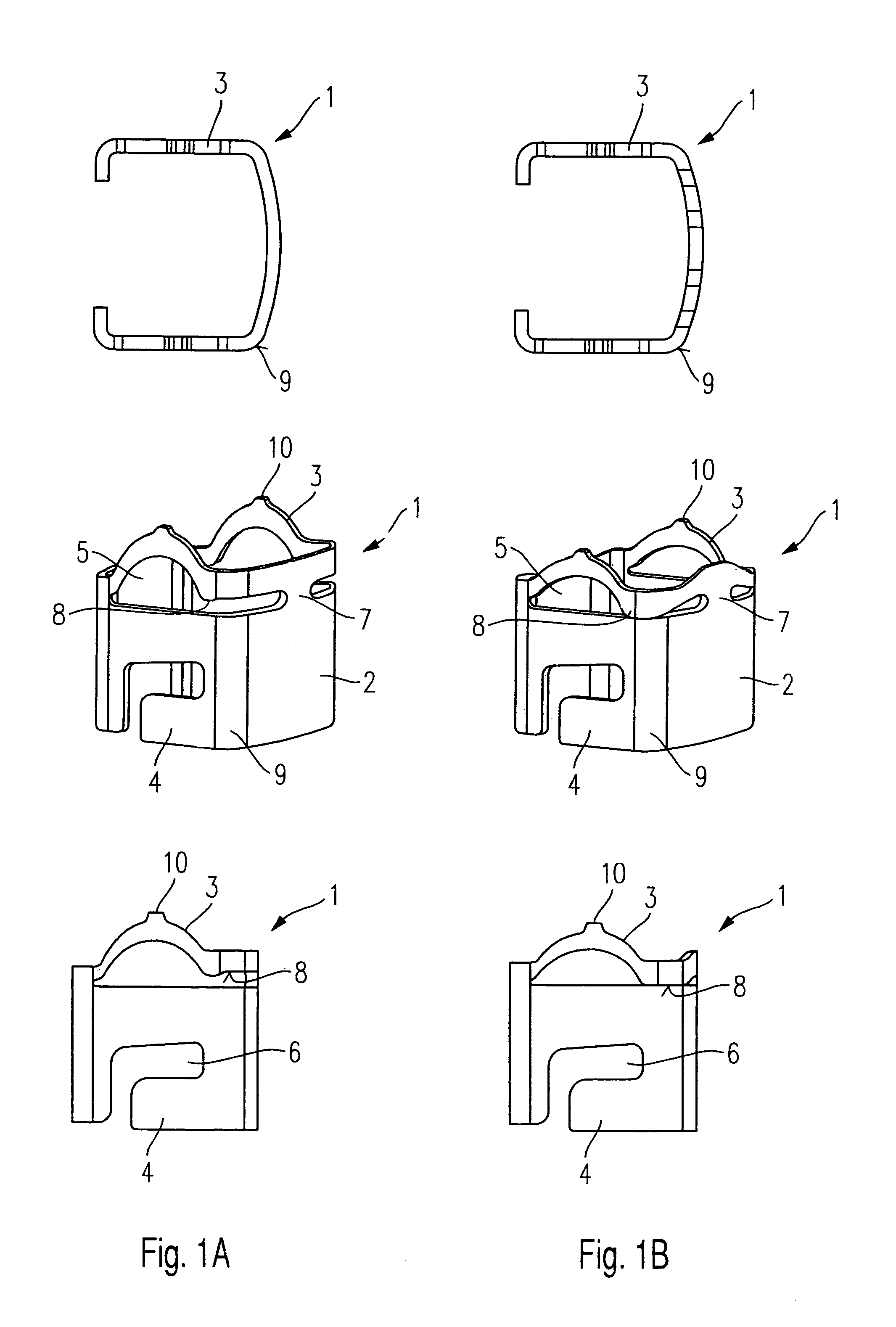
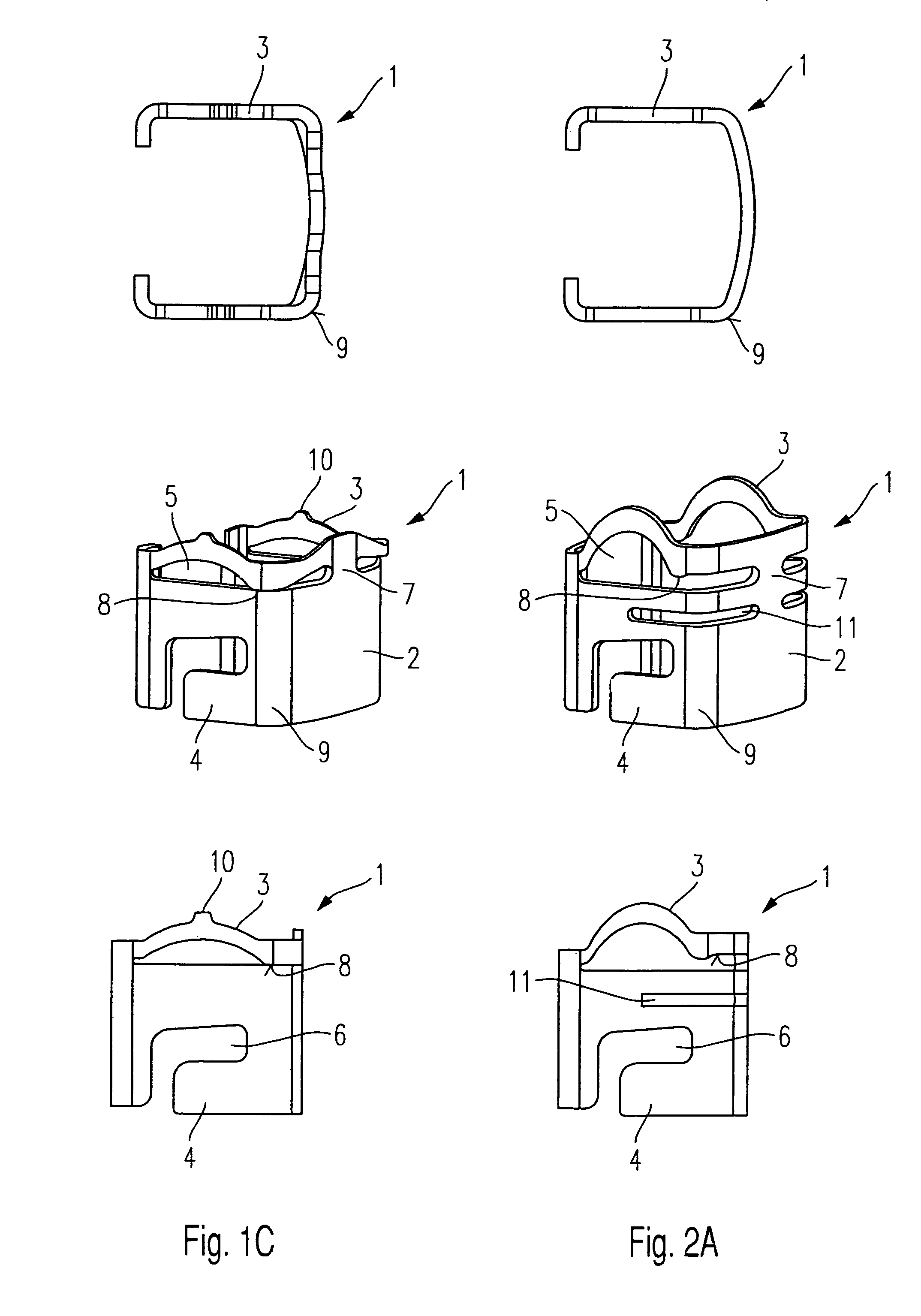
[0014]FIGS. 1A through 1C and 2A through 2C show in the same representation various schematic views of two exemplary embodiments of support elements 1 according to the present invention for fixing fuel injectors in position in a cylinder head of an internal combustion engine and for connecting the fuel injectors to a fuel distribution line.

[0015]In each case, the upper row of figures shows a top view, the middle row of figures shows a perspective view, and the lower row of figures shows a side view of support elements 1 developed according to the present invention. The left column of figures shows support element 1 in a ready-to-fit, but non-loaded state, while the middle column of figures shows support element 1 in each case in a preloaded state, and the right column of figures shows the support element in an fully installed and loaded state.

[0016]Support element 1 includes in each case a clasp 2, which embraces the fuel injector, and clips 3 developed at clasp 2, tabs 4 and legs 1...


PUM


Abstract

A support element for the mutual support of a fuel injector in a valve seat, in particular of the valve seat of a cylinder head of an internal combustion engine, and of the fuel injector at a fuel distribution line has a clasp and thereon developed radially and axially deformable clips.

Description

FIELD OF THE INVENTION[0001]The present invention relates to a support element for setting a fuel distribution line apart from a fuel injector inserted in a cylinder head of an internal combustion engine.BACKGROUND INFORMATION[0002]A mounting device for mounting a fuel injector on an intake manifold is already known from German Published Patent Application No. 29 26 490, according to which a mounting element axially fixes the fuel injector to the fuel distribution line or to a plug nipple, the mounting element being designed as a U-shaped securing clasp having two legs which are elastic in the radial direction. In the assembled state, the securing clasp engages in matching recesses of the plug nipple and is snapped into place in a recess in a connection piece of the fuel injector, the recess being designed as an annular groove. The axial clearance between the recesses and the securing clasp as well as between the annular groove and the securing clasp should be kept small, in order t...

Claims


Application Information

Patent Timeline
Patent Type & Authority Patents(United States)
IPC IPC(8): F02M61/14F02M61/12F02M1/00F02M55/02F02M35/10F02M61/16
CPCF02M35/10F02M35/10216F02M61/14
Inventor SCHEFFEL, MARTINANDORFER, MARTINSCHOLZ, ROCCO
Owner ROBERT BOSCH GMBH
Why Eureka
Try Eureka