

Method and apparatus for microfluidics education
a microfluidics and microfluidic system technology, applied in the field of microfluidics education, can solve the problems of inability to provide a more comprehensive/multi-component microfluidic system, no single microfluidic system training system or apparatus available in the market,
- Summary
- Abstract
- Description
- Claims
- Application Information
AI Technical Summary
Benefits of technology
Problems solved by technology
Method used
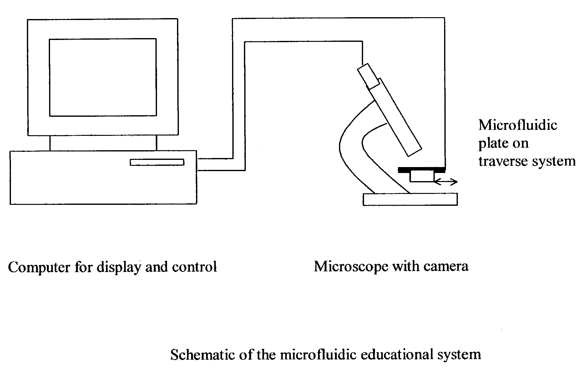
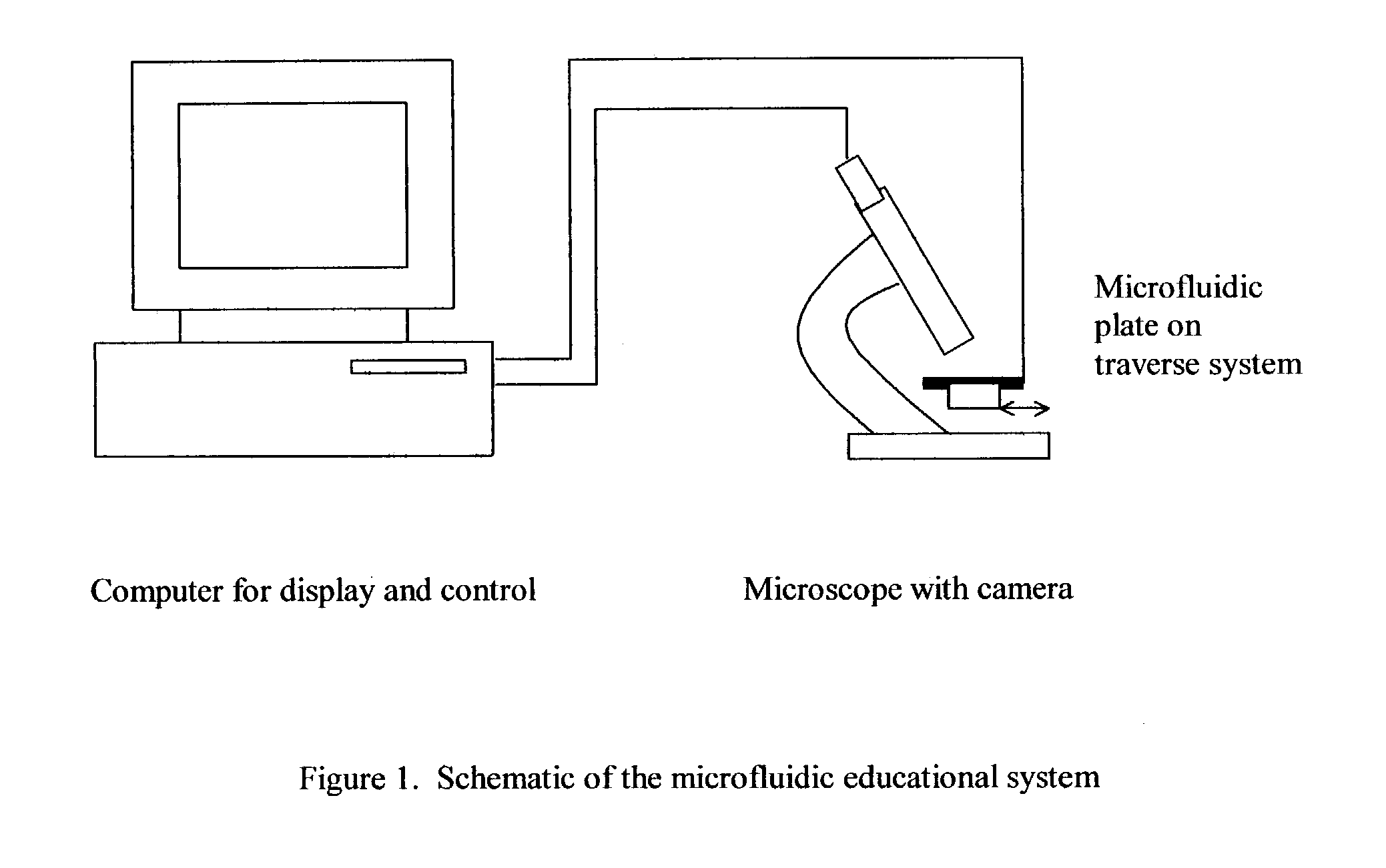
Image

Examples
experiment 1
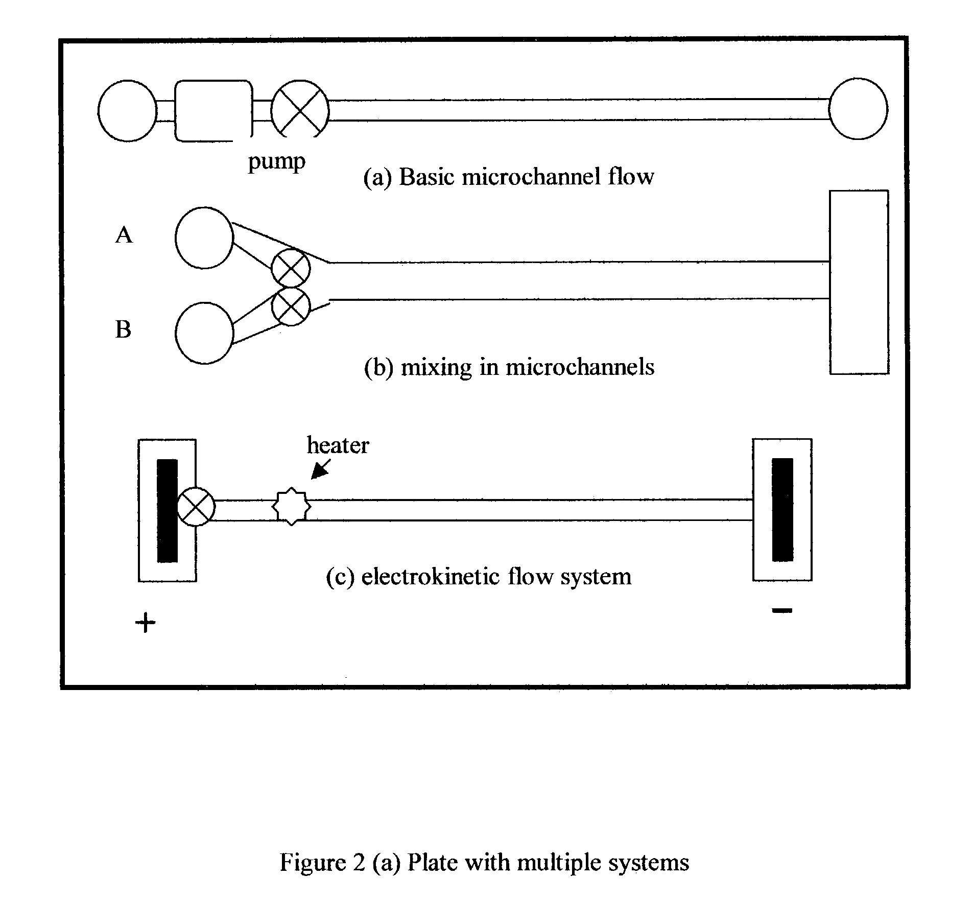
Operation of a Simple Microfluidic Channel Using a Micropump and Measurement of Flow Rate Versus Pressure Drop in the Channel
[0027]The microvalve is set to fully open position and the reservoir on the left side and the microchannel up to the pump is filled with a liquid such as water using a syringe or a pressurized container. A dye may be added to the water before filling the reservoir for better observation. The pressure across the pump is measured using a sensitive pressure transducer. The average flow rate is obtained by measuring the time taken to empty the reservoir and knowing the volume of the reservoir (flow rate=(reservoir volume) / (time taken to empty the reservoir)). The backpressure for the pump is increased by constricting the flow downstream of the pump by a small needle valve or by introducing other constrictions in the flow downstream. The experiment is repeated for a few backpressure settings. By plotting the pressure vs. flow rate from the resulting data, the chara...
experiment 2
Mixing of Two Liquids in a Microchannel
[0028]The reservoirs are filled with a red dye and a blue dye. The liquids are pumped into the channel continuously and due to the laminar flow of the two liquids in the channel, it will be observed that the two fluids barely mix but flow as individual “layers” in the channel. Then the two fluids are pumped in alternating fashion so that small slugs (of the order of 500 microns length) of alternate red and blue fluids are seen in the beginning of the channel. It will be observed that as these slugs move to the other end of the channel, the two fluids get mixed and the distinct demarcation of the slugs disappear due to the increased surface area of interaction between the two fluids.
experiment 3
Electro-Osmotic Flow
[0029]The microchannel is filled with an electrolytic solution such as sodium chloride solution followed by the addition of some microspheres in the electrolyte solution for visualizing the flow. A DC voltage supply (10–50 V) is connected to the two electrodes in the reservoirs of the system. When the voltage supply is turned on one can then observe the fluid flow due to the migration of the ions near the wall of the microchannels.
PUM
 Abstract
Description
Claims
Application Information