Vehicle-mounted generator

a generator and vehicle technology, applied in the direction of electric generator control, machine/engine, renewable energy generation, etc., can solve the problems of low efficiency of solar cells, no practical design has been developed for utilizing this alternative power source, and major permanent environmental changes, so as to prolong the battery life and improve the fuel efficiency of the motor vehicle.

Inactive Publication Date: 2007-05-01
MCDAVID JR WILLIAM K
View PDF45 Cites 94 Cited by
  • Summary
  • Abstract
  • Description
  • Claims
  • Application Information

AI Technical Summary

Benefits of technology

[0010]In another aspect, the present invention is a vehicle-mounted generator for improving fuel efficiency of a motor vehicle having a drive train comprising an internal combustion engine that drives a transmission connected to a drive shaft. The generator includes a rigid cylindrical housing forming an enclosed interior chamber. The housing includes an inlet located on one side of a central longitudinal drive shaft for asymmetrically inputting wind into the interior chamber, and an outlet located at a first end of the housing. The device also includes means for mounting a second end of the housing to the motor vehicle in a position such that relative wind, produced by the combination of ambient wind and motion of the vehicle, is directed into the inlet. A spiraling parabolic deck forms a floor of the interior chamber, and spirals around the central longitudinal shaft from the second end of the housing to the outlet at the first end of the housing. A turbine is mounted on the drive shaft within the outlet for converting wind energy to mechanical energy as the wind passes through the turbine. The device also includes an electrical generator co...

Problems solved by technology

However, this requires major permanent environmental changes to the areas where dams are built and reservoirs rise.
This is particularly true for sources that are non-polluting and inexhaustible.
To date, however, no practical design has been developed for utilizing this alternative power source due, primarily, to the very low efficiency of solar cells.
This is an inefficient design because energy is extracted from the wind by reducing the wind velocity as it passes through the propeller.
The use of such massive blades, however, has its own disadvantages.
First, the propellers are known to kill or injure thousands of large birds each year.
Second, the mass...

Method used


Image

  • Vehicle-mounted generator
  • Vehicle-mounted generator
  • Vehicle-mounted generator

Examples


Embodiment Construction

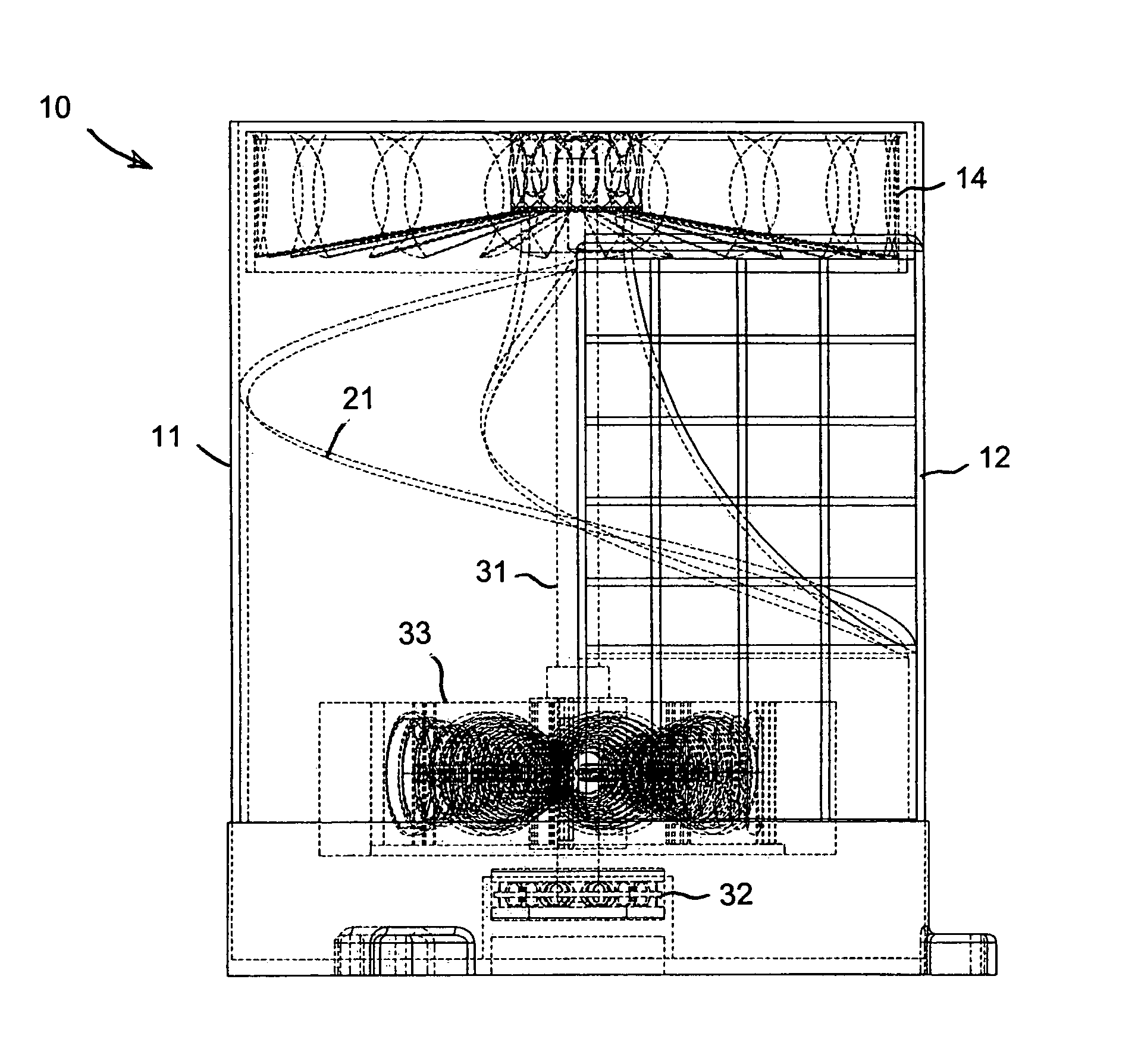
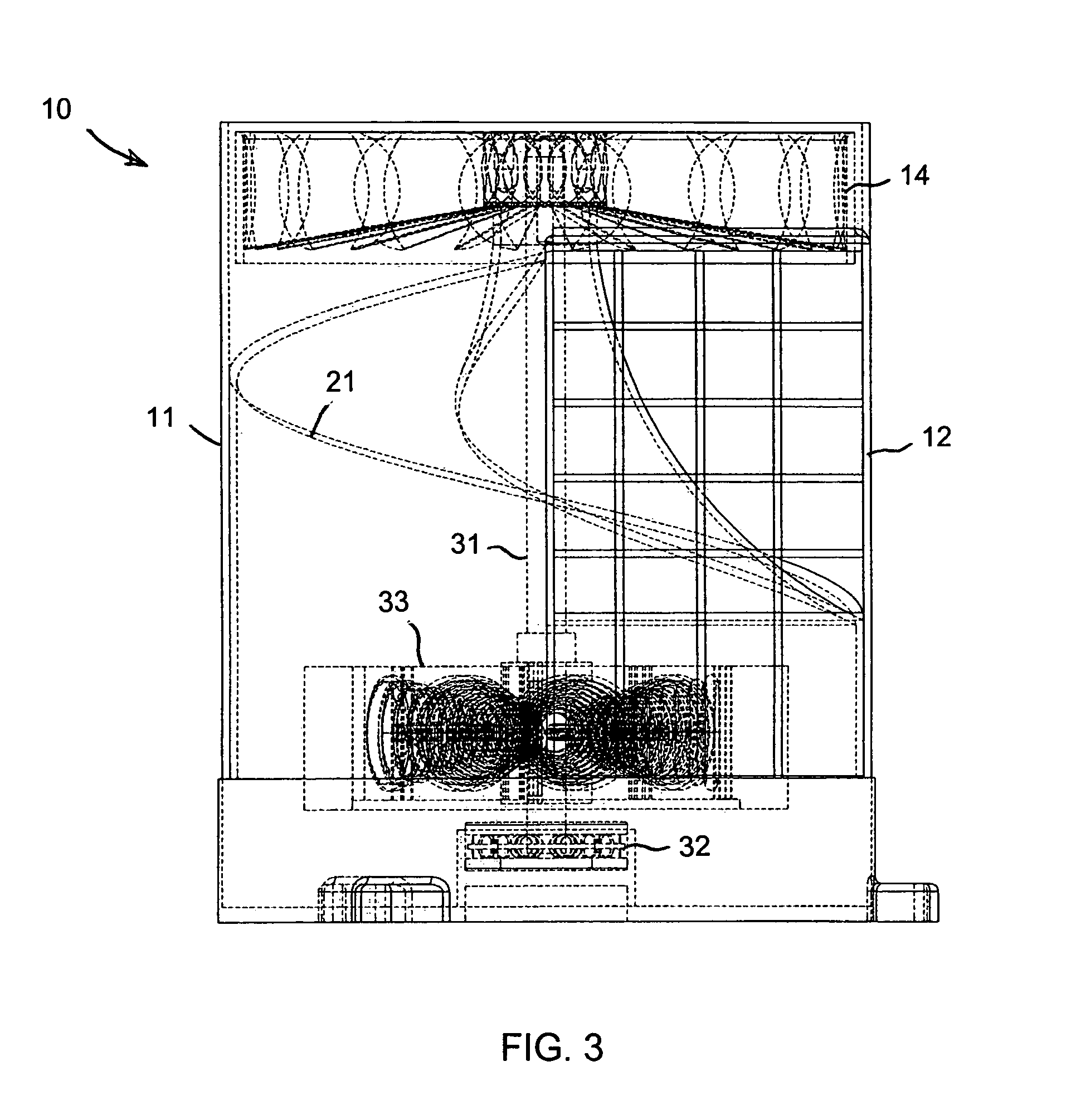
[0024]The present invention is a high-efficiency generator that mounts on a moving vehicle and, in one embodiment, generates mechanical or electrical energy from the relative wind created by the combination of the ambient wind and the motion of the vehicle. In another embodiment, the present invention mounts on a water-borne vehicle and generates mechanical or electrical energy from the flow of the water created by the motion of the vehicle. The terminology utilized herein generally addresses the wind-powered embodiment, although the description is also applicable to the water-powered embodiment. In either embodiment, the energy generated by the invention may then be utilized to directly perform work, to power an electric motor, or to recharge one or more batteries.

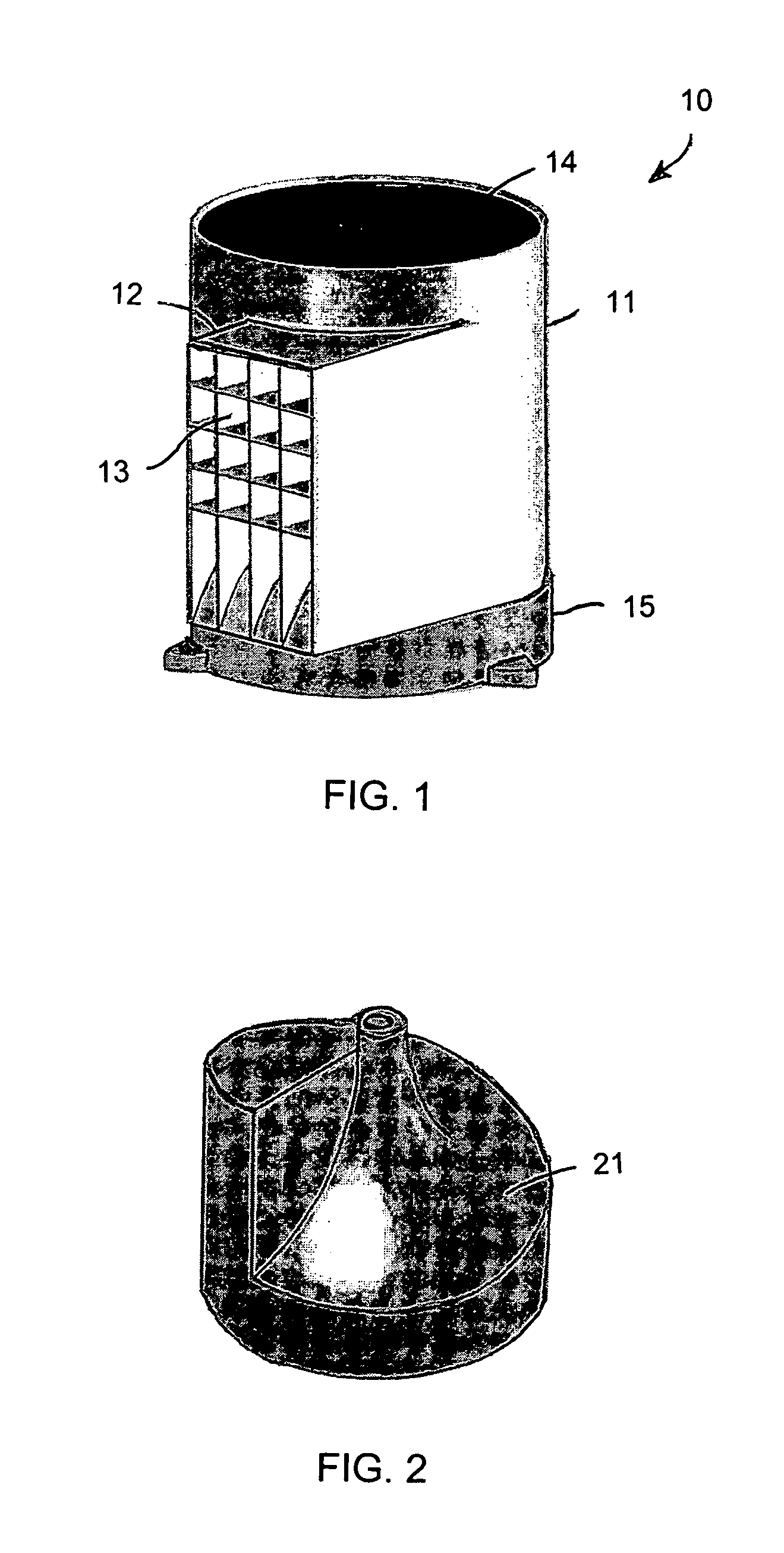
[0025]FIG. 1 is a perspective view of the generator 10 illustrating a housing 11 in one embodiment of the present invention. The housing is generally cylindrical, and mounts at its base to a vehicle. An air inlet 12 is at...


PUM


Abstract

A vehicle-mounted generator is powered by relative wind produced by the combination of ambient wind and motion of the vehicle, or by movement of water when mounted on the hull of a water-borne vehicle. A rigid cylindrical housing forms an enclosed interior chamber. Wind asymmetrically enters the chamber through an inlet located on one side of a central longitudinal drive shaft, and exits through an outlet located at the top of the housing. A spiraling parabolic deck forms a floor of the interior chamber, and spirals around the central longitudinal shaft from the bottom of the housing to the outlet at the top. A turbine mounted on the drive shaft within the outlet converts energy of the exiting wind to mechanical energy. An electrical generator converts the mechanical energy into electrical energy for recharging a battery or powering an electric motor.

Description

BACKGROUND OF THE INVENTION[0001]The present invention relates generally to electrical generation and energy conversion devices, and more particularly to a vehicle-mounted generator that converts the energy of wind or flowing water to mechanical or electrical energy.[0002]The use of wind or flowing water to provide power for various uses dates back many centuries. In modern times, wind and water have been used to generate electricity. Hydroelectric generating plants have been used to generate large quantities of electrical energy for widespread distribution. However, this requires major permanent environmental changes to the areas where dams are built and reservoirs rise. Wind-powered devices, in general, have been used to perform mechanical work, or to generate electricity, only on a limited scale. With the ever-increasing demand for additional or alternative energy sources, all possible sources are being given more scrutiny. This is particularly true for sources that are non-pollu...

Claims


Application Information

Patent Timeline
IPC IPC(8): B60K11/00
CPCB60K6/48B60K16/00F03D9/002F03D11/04B60K2016/006B63B35/44B63B2035/4466F05B2210/16F05B2240/931F05B2240/941Y02E10/727Y02T10/6221Y02T10/90Y10S903/903Y02E10/725F03D13/20F03D9/25Y02E60/16Y02E10/74F03D9/32F03D9/12F03D3/04Y02T10/62Y02E70/30
Inventor MCDAVID, JR., WILLIAM K.
Owner MCDAVID JR WILLIAM K
Why Eureka
Try Eureka