Surveillance device detection utilizing non linear junction detection and reflectometry

Active Publication Date: 2007-05-01
RES ELECTRONICS INT
View PDF31 Cites 19 Cited by
  • Summary
  • Abstract
  • Description
  • Claims
  • Application Information

AI Technical Summary

Benefits of technology

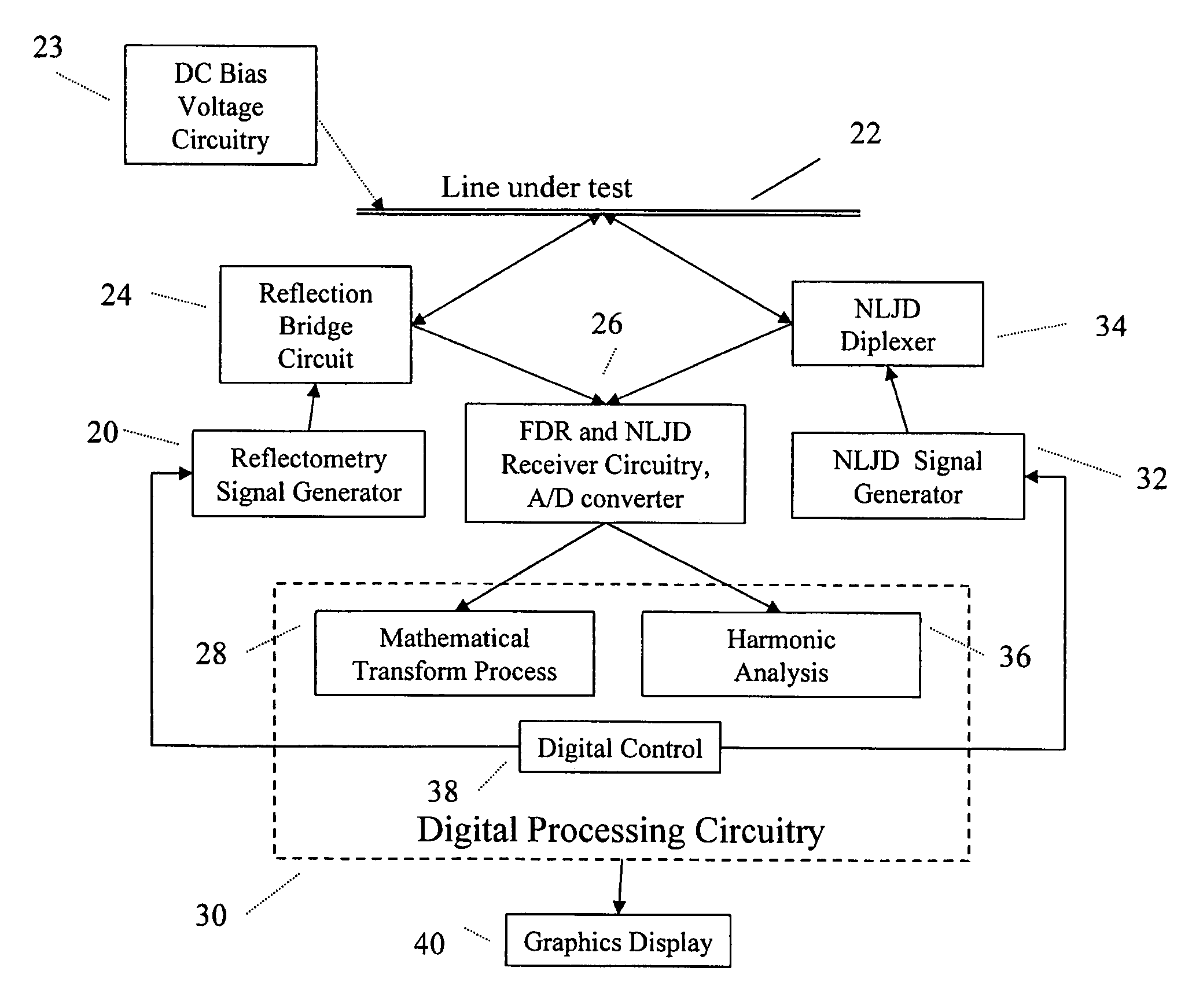
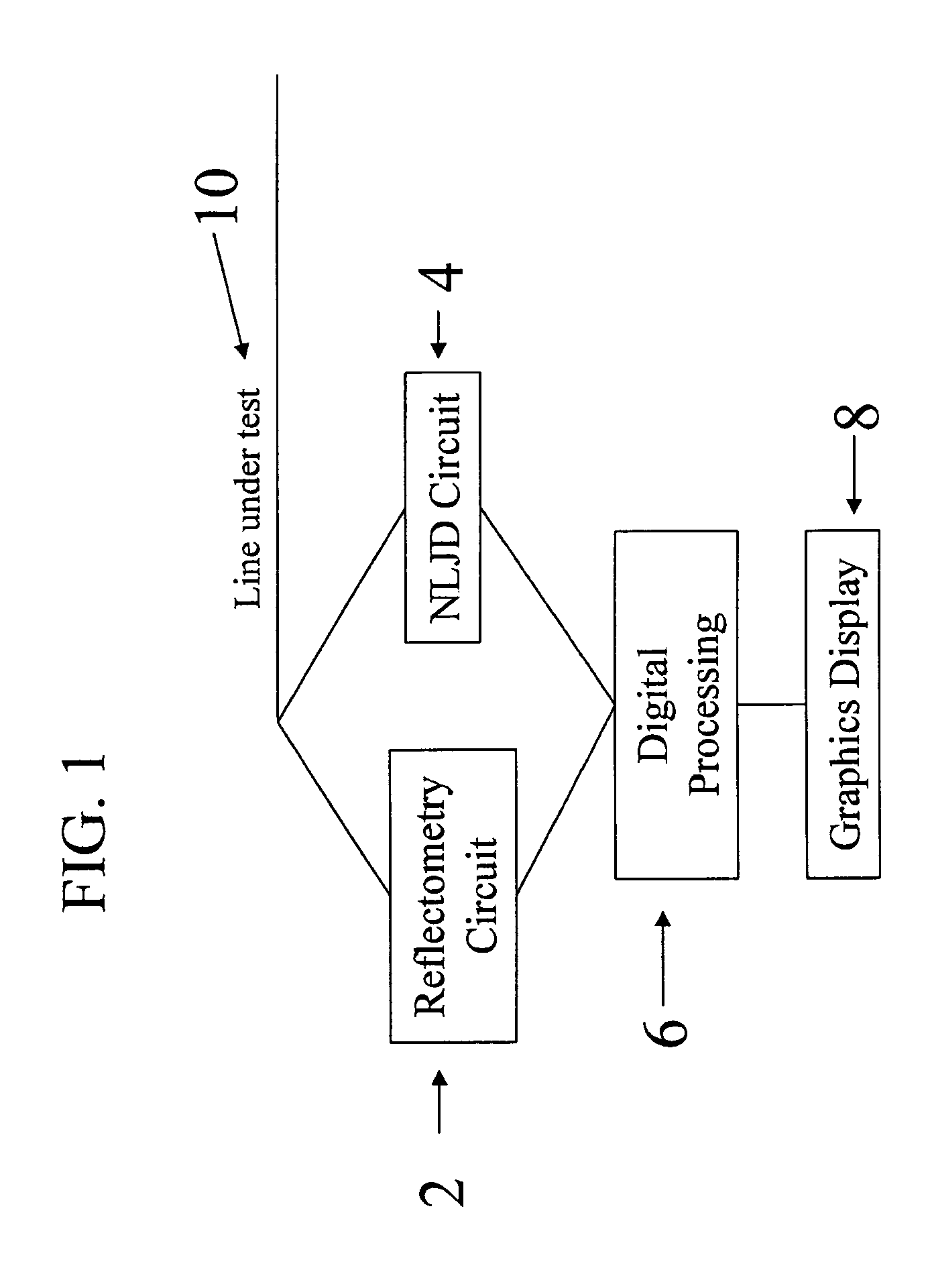
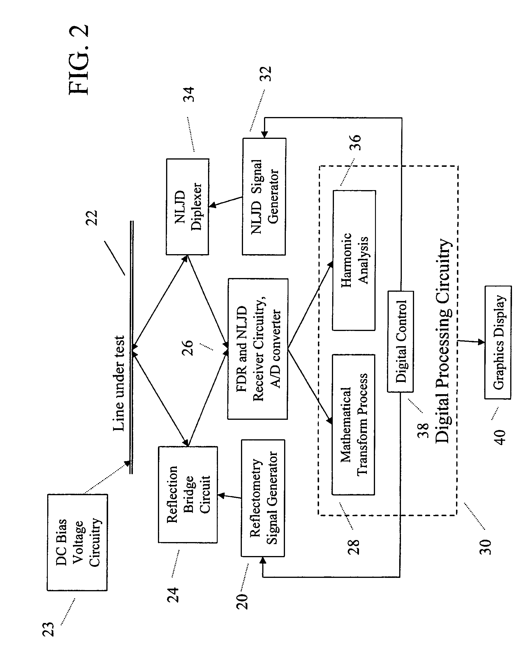
[0011]An embodiment of the present invention is directed toward a method of detecting the presence of dissimilar metal/corrosive junctions and surveillance devices coupled to a transmission line. In accordance with the method, a reflectometry operation is performed on the transmission line to locate any impedance anomalies on the transmission line. The reflectometry operation may be based on time domain reflectometry technology or frequency domain reflectometry technology. However, frequency domain reflectometry is the preferred method due to the fact that it is potentially less damaging to the normal operating circuitry associated with the transmission line. This is because a time domain reflectometry process uses a high power narrow pulse that could potentially cause damage to some circuitry. Conversely, a frequency domain reflectometry process uses a lower power frequency swept waveform and relies on digital signal processing integration for improved sensitivity. Using either reflectometry process, a distance to any impedance anomalies located on the transmission line is determined. In addition, the reflectometry processes may be used to determine additional information regarding the capacitive, inductive, and resistive nature of the impedance anomaly based on the shape of the graph produced by the reflectometry process. A non-linear junction device detection operation is also performed on the transmission line to classify a

Problems solved by technology

This is because a time domain reflectometry process uses a high power narrow pulse that could potentially cause damage to some circuitry.
However, if the reflectometry operation is performed on a dry line, i.e. a line that is not connected to it's normal electronic operating circuitry, a bala

Method used


Image

  • Surveillance device detection utilizing non linear junction detection and reflectometry
  • Surveillance device detection utilizing non linear junction detection and reflectometry
  • Surveillance device detection utilizing non linear junction detection and reflectometry

Examples


Embodiment Construction

[0023]Embodiments of the present invention are directed toward a method and apparatus for detecting the presence of concealed surveillance devices coupled to a transmission line using a combination of either time or frequency domain reflectometry analysis and non-linear junction detection processes. The combination of these processes reduces the time and effort required to inspect a transmission line for covert surveillance devices while improving the likelihood of locating any such devices.

[0024]In accordance with a preferred embodiment of the present invention, the first step in detecting a covert surveillance device coupled to a transmission line is to perform a time domain or frequency domain reflectometry operation to determine the presence and location of any reflecting discontinuities or impedance anomalies on the transmission line under test. Once the anomalies and discontinuities have been located, a non-linear junction detection operation is performed on the line to determ...


PUM


Abstract

An apparatus for detecting concealed surveillance devices coupled to a transmission line uses either a time domain or frequency domain reflectometry operation to locate any impedance anomalies on the transmission line and a non-linear junction detection operation to classify the located impedance anomalies as semiconductor or non-semiconductor based anomalies. The reflectometry operation utilizes the reflection of a test signal to determine the distance to any reflecting impedance anomalies on the transmission line that may be indicative of an electronic device being coupled to the transmission line. The non-linear junction detection operation then compares the amplitudes of re-radiated second and third harmonics of a transmitted fundamental frequency signal to determine if the reflecting impedance anomalies are the result of a semiconductor based non-linear junction. A DC bias voltage and a balanced load may be added to the transmission line to enhance the line's response to the test signals. Any unidentified semiconductor based anomalies are manually inspected to determine if they represent convert surveillance devices.

Description

FIELD OF THE INVENTION[0001]The present invention relates generally to the detection of surreptitious surveillance devices. More particularly, the present invention relates to the use of either time or frequency domain reflectometry and non-linear junction detection to determine the presence, location and nature of a surreptitious surveillance device attached to a communication line.CROSS-REFERENCES TO RELATED APPLICATIONS[0002]Not ApplicableSTATEMENT REGARDING FEDERALLY SPONSORED RESEARCH OR DEVELOPMENT[0003]Not ApplicableREFERENCE TO SEQUENCE LISTING OR COMPUTER PROGRAM LISTING APPENDIX[0004]Not ApplicableBACKGROUND OF THE INVENTION[0005]Counter surveillance professionals are obviously interested in locating concealed surveillance devices. Often these concealed surveillance devices are coupled to communication or power transmission lines so that they can monitor any transmissions on the line or use the lines to complete their own covert transmissions. The coupling of the surveilla...

Claims


Application Information

Patent Timeline
IPC IPC(8): G01R31/11
CPCG01R31/11
Inventor BARSUMIAN, BRUCE R.JONES, THOMAS H.LITER, CHARLES A.
Owner RES ELECTRONICS INT
Why Eureka
Try Eureka