Apparatus and method for cooling electronics and computer components with managed and prioritized directional air flow heat rejection

a technology of electronics and computer components, applied in the direction of cooling/ventilation/heating modifications, electrical apparatus casings/cabinets/drawers, instruments, etc., can solve the problems of compromising reliability and ultimately the functionality, more difficult to provide effective cooling to critical components, and higher heat loads

Active Publication Date: 2007-05-01
ROCKY RES INC
View PDF24 Cites 143 Cited by
  • Summary
  • Abstract
  • Description
  • Claims
  • Application Information

AI Technical Summary

Problems solved by technology

Cooling of the most important electronic components is not necessarily achieved by providing maximum cooling air speed over all components which can increase the air temperature unnecessarily from cooling non-critical components capable of operating reliably at elevated temperatures or operating at lower energy densities not leading to a critical operating temperature before such air actually reaches the more critical component, and whereby the now higher air temperature makes it more difficult to provide effective cooling to the critical component.
Methods and components for achieving improved cooling and thermal management of electronic components are called for as faster processing speeds require higher power levels for electronics and where higher resolutions require higher power levels for displays, both leading to higher heat loads, which need to be removed in order to maintain operating temperatures of the components below critical temperatures at which the reliability and ultimately the functionality is compromised.
In such cases the housing or a portion of the housing is sealed and the necessary heat transfer required to manage the temperature of the heat generating electronic components is further limited in that it must be accomplished with means providing heat transfer through the housing walls, often inadequate because the surface area and thermal conductivity of the housing wall is usually incapable of transferring a significant portion of the heat to be rejected, nor is the housing wall commonly in good thermal contact with the heat generating components.

Method used


Image

  • Apparatus and method for cooling electronics and computer components with managed and prioritized directional air flow heat rejection
  • Apparatus and method for cooling electronics and computer components with managed and prioritized directional air flow heat rejection
  • Apparatus and method for cooling electronics and computer components with managed and prioritized directional air flow heat rejection

Examples


Embodiment Construction

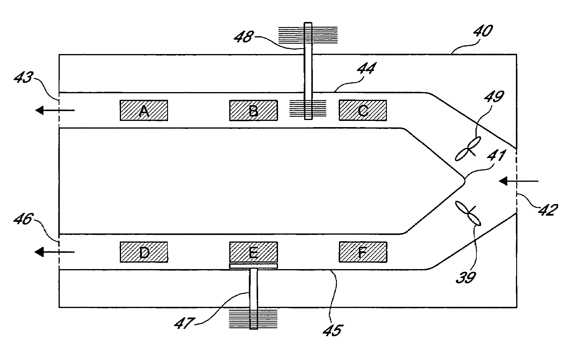
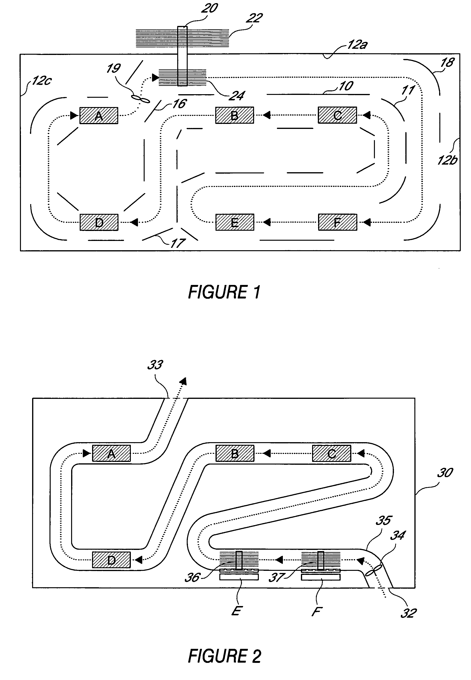
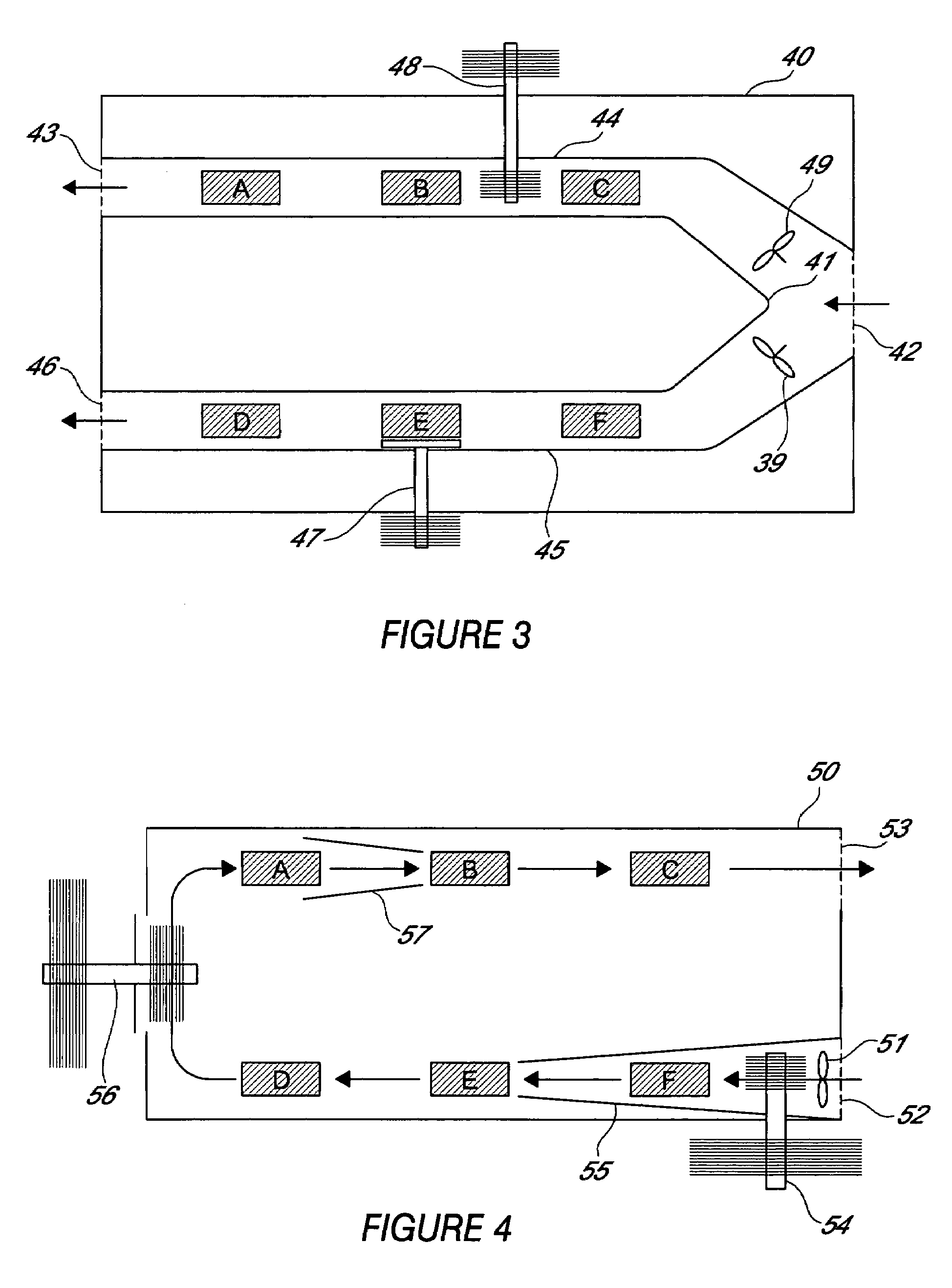
[0011]In the method and apparatus described herein and illustrated in the drawings, management of the air flow is used to direct a stream of air generated or created by the fans sequentially to the heat-generating electronic components and / or heat exchangers also referred to herein as cooling components and “heat sinks”. The air flow direction is based on prioritization of the power densities and operating temperature reliability limits and corresponding cooling requirements of the different heat-generating electronic components. The stream of air is directed by using baffles and / or ducts positioned inside the housing. A plurality of baffles are positioned to cooperate with one another and / or the interior housing wall surface to form one or more passageways for directing the forced air to contact and sequentially cool the plurality of heat generating components. One or more flow splitters may also be used with or formed by the baffles to separate an air stream into a plurality of co...


PUM


Abstract

An apparatus and method of cooling a plurality of electronic components in a housing using one or more fans cooperating with baffles or ducts for directing a stream of air sequentially to the components or heat exchangers for the components. Direction of the air stream to the components is based on predetermined cooling prioritization of the plurality of components.

Description

BACKGROUND OF THE INVENTION[0001]The housing, casing or container for a computer defines a space in which various heat-generating electronic components are secured, typically mounted on boards which themselves are secured in the housing. It is known to use heat sinks, for example conductive or phase change heat exchange components at or in thermal communication with specific components to cool the heat generating electronic components and further provide heat dispersion with one or more fans. Typically the fans move air for the purpose of heat removal from the above mentioned conductive or phase change components or in some cases directly from the electronic components. Enhanced surface designs for improved convective heat transfer are sometimes applied. Fans or blowers are also used to move or circulate air within the space of the casing to provide convection and thereby heat removal via the air without any priority regard to specific components or move air to provide airflow from ...

Claims


Application Information

Patent Timeline
Patent Type & Authority Patents(United States)
IPC IPC(8): G06F1/16H05H7/20
CPCG06F1/20
Inventor ROCKENFELLER, UWE
Owner ROCKY RES INC
Why Eureka
Try Eureka