
Information recording/reading head

a technology of information recording and reading head, which is applied in the field of information recording/reading head, can solve the problems of preventing the improvement of a recording density, difficult to achieve, and the requirement for using information is unending, so as to maintain or improve the accuracy of information recording and reproduction. the effect of durability

Inactive Publication Date: 2007-05-01
PIONEER CORP
View PDF1 Cites 24 Cited by
  • Summary
  • Abstract
  • Description
  • Claims
  • Application Information

AI Technical Summary

Benefits of technology

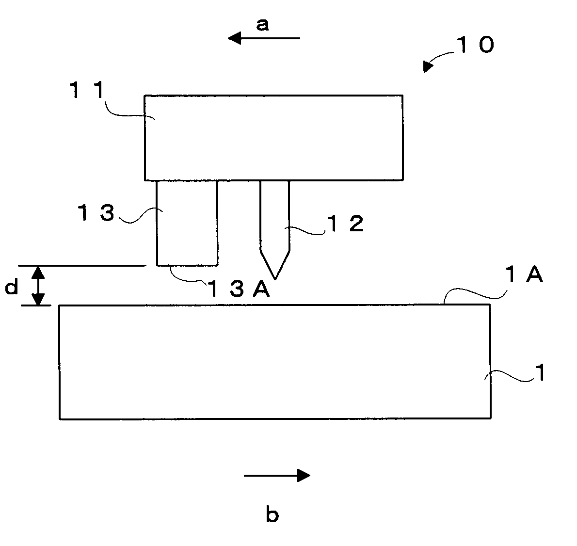
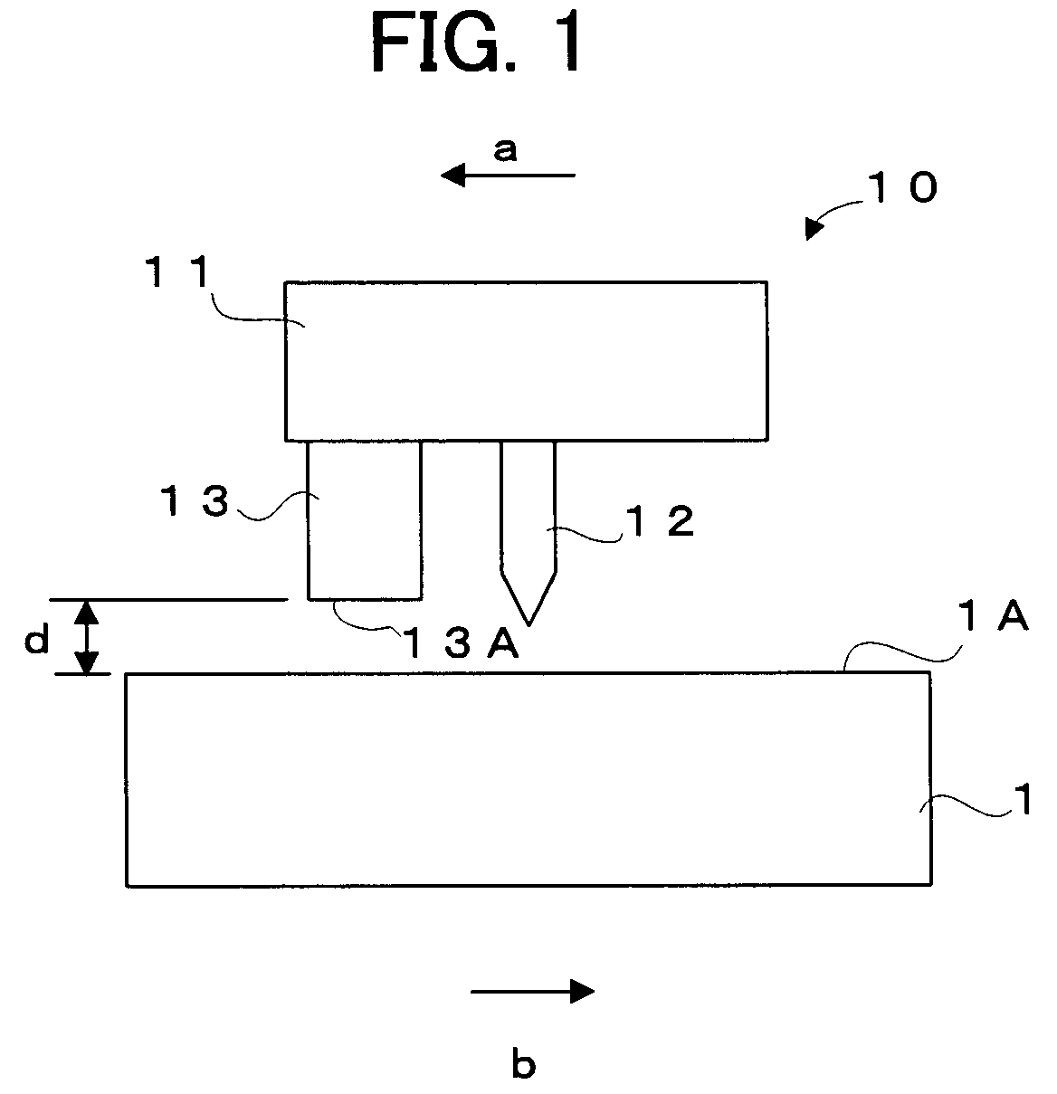
The present invention provides an information recording / reading head that can maintain or improve information recording and reproduction accuracy even if there are dusts, or protect the probe to prevent failure and to improve durability. This is achieved by a head with a support portion that can change its position relative to the recording surface, a probe attached to the support portion and extending to the recording surface, and a guard attached to the support portion and placed in the vicinity of the probe. The guard is placed at a predetermined distance from the recording surface and is positioned at least on the forward side of the probe in a situation where the position of the support portion is being changed.

Problems solved by technology

However, growing the requirement for using information is unending, and a recording / reproducing apparatus which allows the high density, large capacity recording is eagerly desired to be developed.
In general, in a magnetic recording medium, the deterioration of recording bits, which is caused by thermal fluctuation, prevents the improvement of a recording density.
Therefore, in order to try to improve the recording density, one needs to overcome such limits; however, this is not easy.
However, in the recording / reproducing apparatus using SPM or SNDM, dusts may be attached to the probe in some cases because the probe with a radius on the nanometer order is exposed in the vicinity of a recording surface of the recording medium.
Even inside the sealed case, however, dusts may be made by the abrasion of driving portions of the recording medium and the recording / reproducing mechanism, so that it is difficult to prevent such dusts from attaching to the probe.
Moreover, even when an electric field is applied to the ferroelectric material to record information, a distribution of the electric field to be applied changes in some cases if dusts attach to the probe.
As a result, the electric field is not surely applied, and information recording accuracy decreases.
Moreover, the decrease in the accuracy of recording and reproducing may occur in the same manner, even in the recording / reproducing apparatus of a system for applying heat to a polymer film with a cantilever to record a mark.
Therefore, if the probe or the recording medium is moved with dusts existing between the probe and the recording surface of the recording medium, an external force is applied to the probe, so that the probe may be destroyed.
Moreover, it is also conceivable that dusts collide with the probe in motion, thereby misaligning and destroying the probe.
As a result, a recording / reading head may break down, or the durability thereof cannot be improved.

Method used


Image

  • Information recording/reading head
  • Information recording/reading head
  • Information recording/reading head

Examples


first example

[0067]The first example of the present invention will be explained with reference to FIG. 2 to FIG. 6.

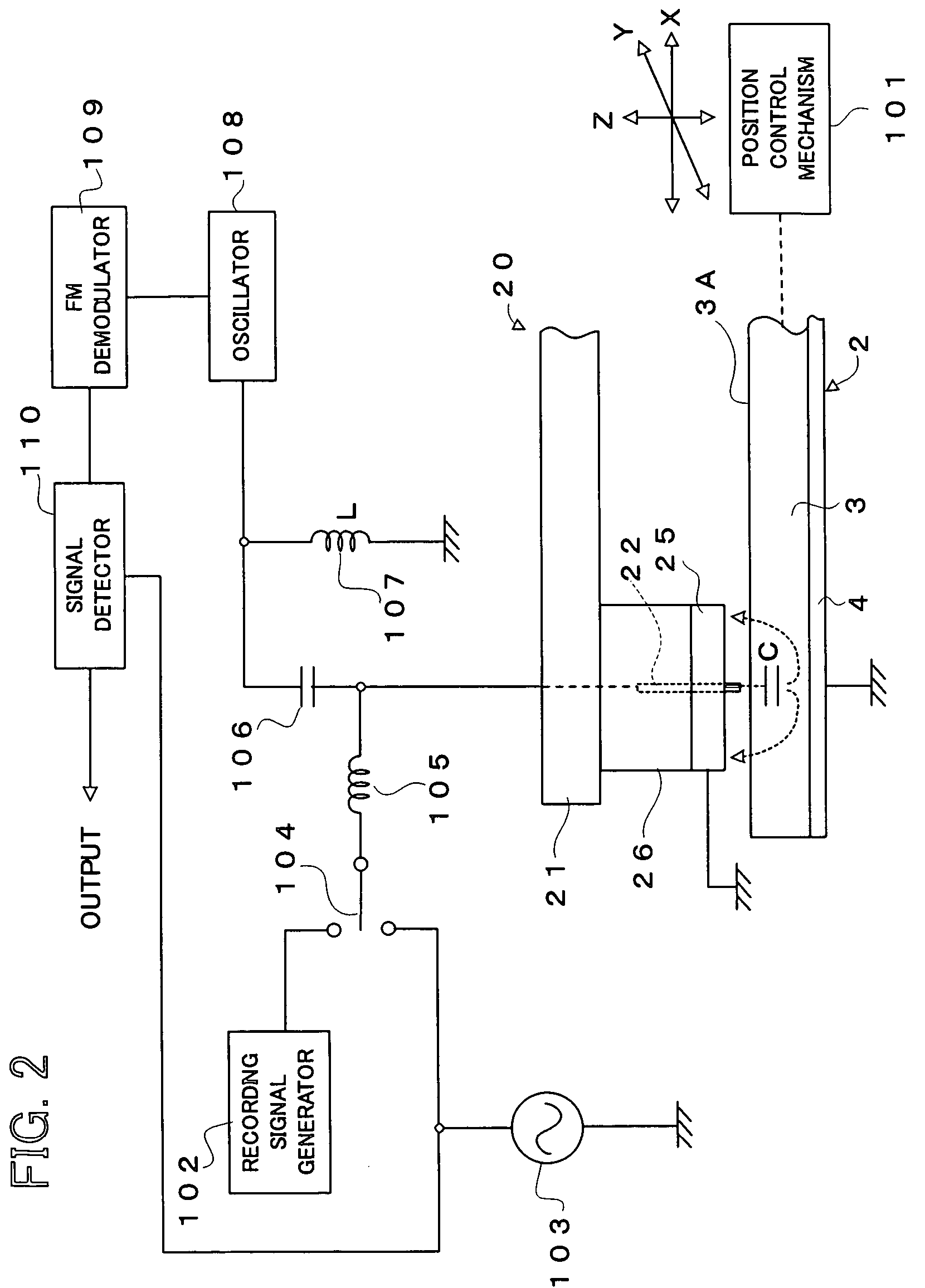
[0068]FIG. 2 is a block diagram showing the construction of a recording / reproducing apparatus which uses an information recording / reading head associated with the first example of the present invention.

[0069]A recording / reproducing apparatus 100 shown in FIG. 2 is an apparatus for recording information, such as music data, picture data, document data or a computer program, in an information recording medium 2 and for reproducing information recorded in the information recording medium 2. The recording / reproducing apparatus 100 uses SNDM as principles of data reproduction. The information recording medium 2 is provided with: a ferroelectric film 3 formed of a ferroelectric material; and a back plate 4. The back plate 4 is earthed.

[0070]The recording / reproducing apparatus 100 is provided with: an information recording / reading head 20 associated with the first example of the present in...

second example

[0100]The second example of the present invention will be explained with reference to FIG. 7. Incidentally, in the second example described below, the same constitutional elements as those in the first example carry the same reference numerals and the explanations of them are omitted.

[0101]FIG. 7 shows the construction and operation of an information recording / reading head associated with the second example. As shown in FIG. 7, an information recording / reading head 30 associated with the second example of the present invention is provided with: a support substrate 31; a probe 32; a guard support portion 33; a piezoelectric driving device 34; and a guard 35.

[0102]The support substrate 31 is substantially the same as the support substrate 21 in the first example. The probe 32, as is substantially the same as the probe 22 in the first example, is also formed by using carbon nanotube, for example. A basal portion of the probe 32 is directly fixed to the support substrate 31. Moreover, t...

third example

[0108]The third example of the present invention will be explained with reference to FIG. 9 and FIG. 10. Incidentally, in the third example described below, the same constitutional elements as those in the first or second example carry the same reference numerals and the explanations of them are omitted.

[0109]FIG. 9 and FIG. 10 show an information recording / reading head associated with the third example of the present invention. FIG. 9 is a cross sectional view of the information recording / reading head viewed from the side. FIG. 10 is a plan view of the information recording / reading head in the FIG. 9 viewed from the direction of arrows II—II.

[0110]As shown in FIG. 9, an information recording / reading head 50 associated with the third example of the present invention is provided with: a support substrate 51; a cantilever 52; a cantilever support portion 53; and a guard 54.

[0111]The support substrate 51 is formed of a silicon substrate, for example, and is placed above the recording s...


PUM

PropertyMeasurementUnit
distanceaaaaaaaaaa
distanceaaaaaaaaaa
distanceaaaaaaaaaa

Abstract

There is provided a circular guard so as to surround the vicinity of a tip portion of a probe mounted on an information recording / reading head, in order to prevent dusts from touching and colliding with the probe.

Description

BACKGROUND OF THE INVENTION[0001]1. Field of the Invention[0002]The present invention relates to an information recording / reading head for recording information in an information recording medium by using a small probe or for reading information recorded in the information recording medium.[0003]2. Description of the Related Art[0004]In general, an optical disk apparatus, a magneto-optical disk apparatus, a Hard Disk Drive (HDD) apparatus, or the like are widely used as a high-density, large-capacity recording / reproducing apparatus. In the beginning, even these recording / reproducing apparatuses were expected to satisfy a requirement for using temporal information because it realized large capacity recording which greatly exceeded the recording capacity of a conventional recording / reproducing apparatus. However, growing the requirement for using information is unending, and a recording / reproducing apparatus which allows the high density, large capacity recording is eagerly desired to...

Claims


Application Information

Patent Timeline
Patent Type & Authority Patents(United States)
IPC IPC(8): G11B9/10G11B9/00G11B9/14G11B7/12G11B7/121G11B9/02G11B9/08G11B9/12G11B11/08G11B23/50
CPCB82Y10/00G11B7/121G11B9/08G11B9/1409G11B9/1418G11B11/08G11B7/12G11B9/02G11B23/50
Inventor MAEDA, TAKANORIONOE, ATSUSHI
Owner PIONEER CORP
Learn More