Multi-level signal clock recovery technique

a multi-level signal and clock recovery technology, applied in pulse technique, dc level restoring means or bias distort correction, baseband system details, etc., can solve the problems of difficult clock recovery of the resulting complex waveform, unit inutility in high speed communication environment, and usually does not detect a high percentage of transitions

Active Publication Date: 2007-05-01
INTERSIL INC
View PDF288 Cites 22 Cited by
  • Summary
  • Abstract
  • Description
  • Claims
  • Application Information

AI Technical Summary

Benefits of technology

[0008]This invention offers an efficient method for recovering the clock or equivalently the symbol timing information of very high-speed ML waveforms. It can be particularly applicable to the clock recovery of ML signals within the receivers of high-speed telecommunication systems.
[0014]Consequently, the invention can threshold the absolute value of the derivative instead of the signed derivative, unlike many conventional clock recovery techniques known in the art that use the sign, positive or negative, of the slope around a nominal sampling point to determine whether a clock should be advanced or delayed.

Problems solved by technology

Clock recovery of the resulting complex waveforms can be difficult, but is critical for data recovery.
Such an approach usually does not detect a high percentage of the transitions of a multilevel signal that are important to determine the clock signal.
However, such units are not useful in the high speed communications environment because of the processing time needed by these conventional units to extract the clock signals from the multi-level signals.
Such decoding is subject to decoding errors.

Method used


Image

  • Multi-level signal clock recovery technique
  • Multi-level signal clock recovery technique
  • Multi-level signal clock recovery technique

Examples


Embodiment Construction

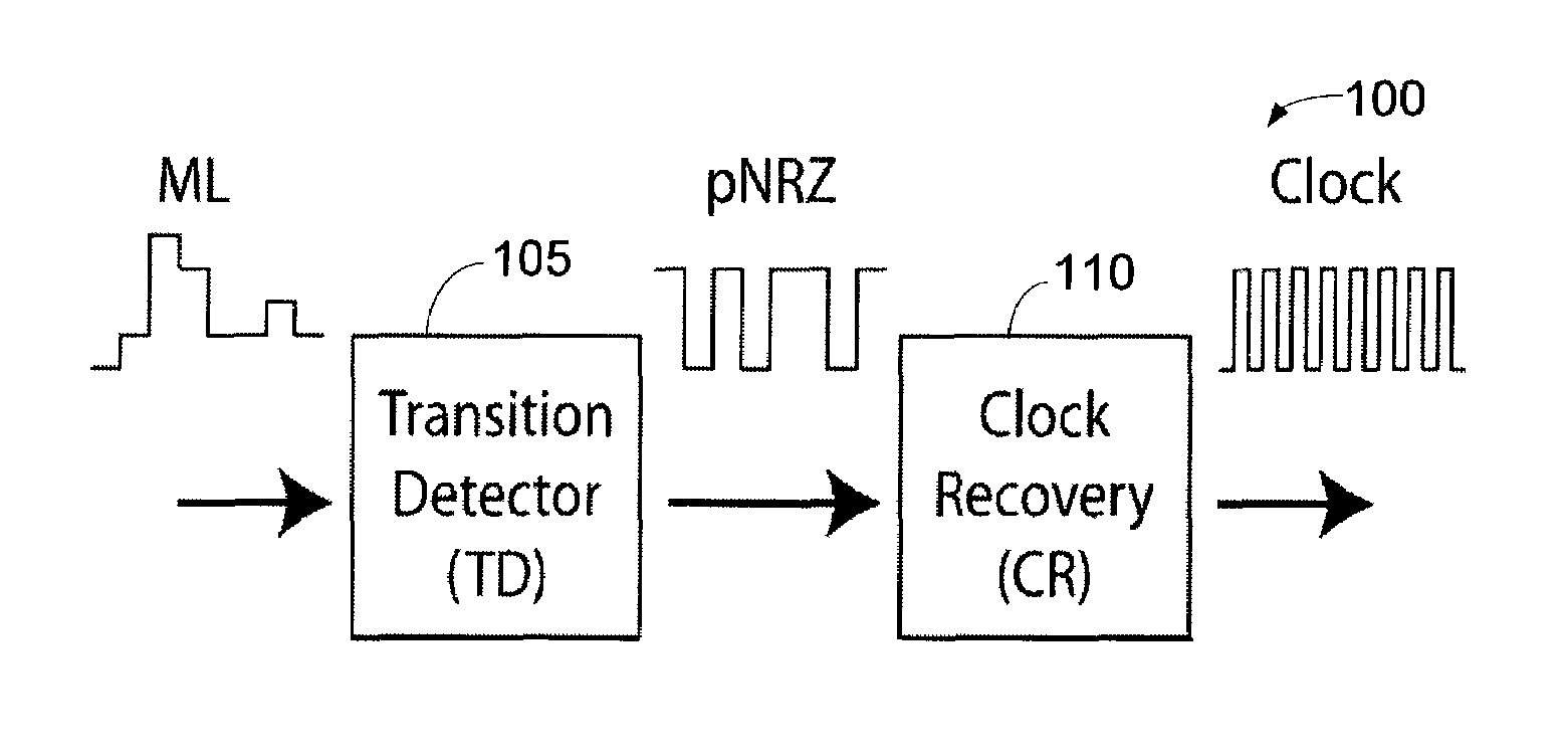
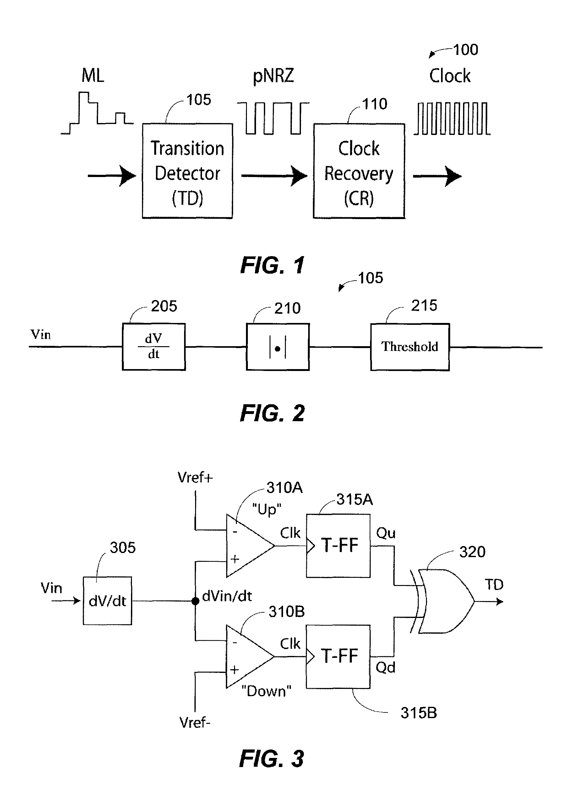
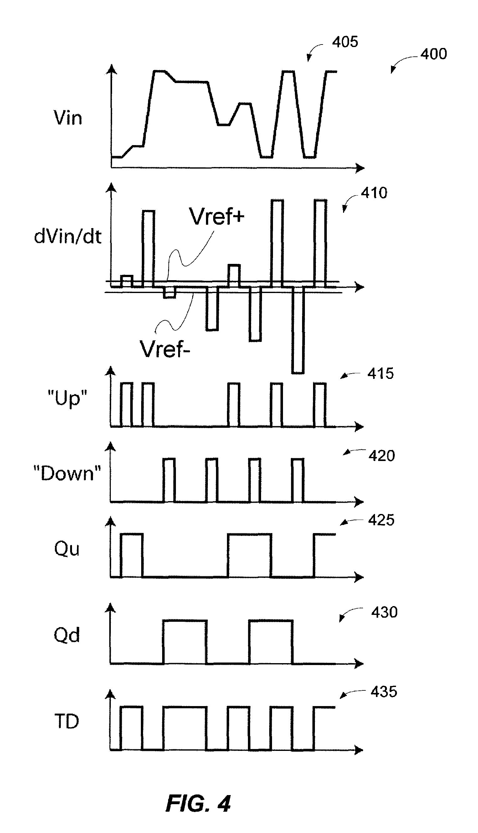
[0036]Clock recovery of a multi-level (ML) signal can be performed in a two-step process. First, the transitions within the ML signal can be detected by a novel transition detector (TD). And second, the output of the TD circuit can comprise a pseudo-non-return-to-zero (pNRZ) signal that can drive a conventional OOK clock recovery (CR) IC. The TD circuit can convert the edges of the ML signal into the pseudo-NRZ (pNRZ) signal. The TD circuit can capture as many transitions as possible to allow the conventional NRZ clock recovery (CR) chip to optimally perform. The TD circuit can differentiate the ML signal in order to detect the ML signal's transitions.

[0037]An exemplary transition detection circuit has been built by the inventors and simulated to operate at 2.7 Giga Symbols per second (Gsym / sec) in a Gallium Arsenide (GaAs) heterojunction bi-polar transistor (HBT) process. In other words, the inventors have fabricated a working model of the present invention. The present invention c...


PUM


Abstract

Clock recovery of a multi-level (ML) signal can be performed in a two-step process. First, the transitions within the ML signal can be detected by a novel transition detector (TD). And second, the output of the TD circuit can comprise a pseudo-non-return-to-zero (pNRZ) signal that can drive a conventional OOK clock recovery (CR) IC. The TD circuit can convert the edges of the ML signal into the pseudo-NRZ (pNRZ) signal. The TD circuit can capture as many transitions as possible to allow the conventional NRZ clock recovery (CR) chip to optimally perform. The TD circuit can differentiate the ML signal in order to detect the ML signal's transitions.

Description

PRIORITY AND RELATED APPLICATIONS[0001]The present application claims priority to provisional patent application entitled, “MULTI-LEVEL SIGNAL CLOCK RECOVERY TECHNIQUE,” filed on Feb. 15, 2002 and assigned U.S. application Ser. No. 60 / 357,362. The entire contents of this provisional application are hereby incorporated by reference.TECHNICAL FIELD[0002]The present invention relates to high speed communications. More particularly, the present invention relates to a system and method for recovering clock signals from multi-level signals in high speed optical and electrical communications.BACKGROUND OF THE INVENTION[0003]In order to obtain increase spectral efficiency and therefore increased data throughput for both optical and electrical data transport systems, complex modulation schemes, such as multilevel (ML) signaling, are desired by the communications industry for both electrical and optical domain applications. Clock recovery of the resulting complex waveforms can be difficult, b...

Claims


Application Information

Patent Timeline
Patent Type & Authority Patents(United States)
IPC IPC(8): H04L25/49H03K5/08H03K5/135H03K5/1534H04L7/033
CPCH03K5/08H03K5/135H03K5/1534H04L7/0087H04L7/033H04L25/4917
Inventor HIETALA, VINCENT MARKKIM, ANDREW JOO
Owner INTERSIL INC
Why Eureka
Try Eureka