Modular electronic fuze

Inactive Publication Date: 2007-05-08
ENGEL BALLISTIC RES
View PDF36 Cites 19 Cited by
  • Summary
  • Abstract
  • Description
  • Claims
  • Application Information

AI Technical Summary

Benefits of technology

[0006]A modular, inventive fuze assembly is provided for use in multiple types of military ordinance. The fuze comprises a base unit having an initiator for arming the fuze; a timer assembly that includes a programmable clock package; a trigger assembly comprising a line monitoring circuit an

Problems solved by technology

The most complex mechanical systems are clockwork driven safety and arming systems.
Such requirements result in fuzes that displace more payload in “man portable weapon systems” where there exists very little room for either the fuze or the payload.
If however, insufficient force is imparted against the plunger/striker, then the fuze will fail to initiate.
Such an insufficient force can occur for example, if there is a glancing blow or the ordnance strikes a soft target.
Because most mechanical fuzes include a combination of both clockwork timing and impact devices, they typically suffer from excessive si

Method used


Image

  • Modular electronic fuze
  • Modular electronic fuze
  • Modular electronic fuze

Examples


Embodiment Construction

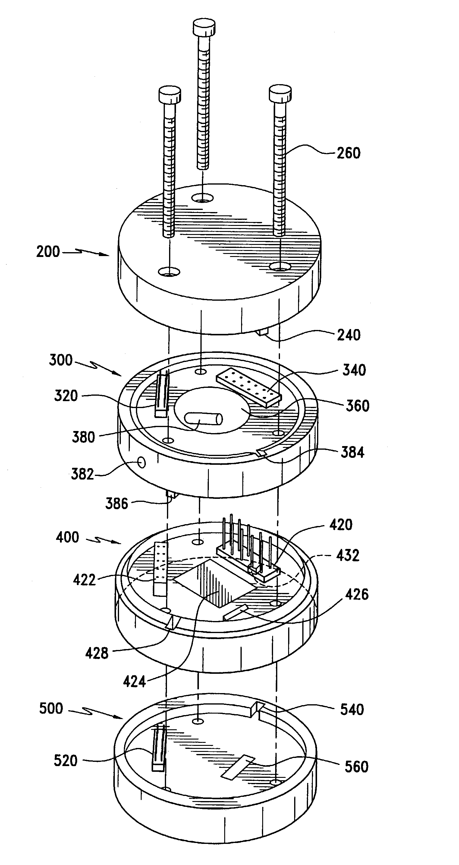
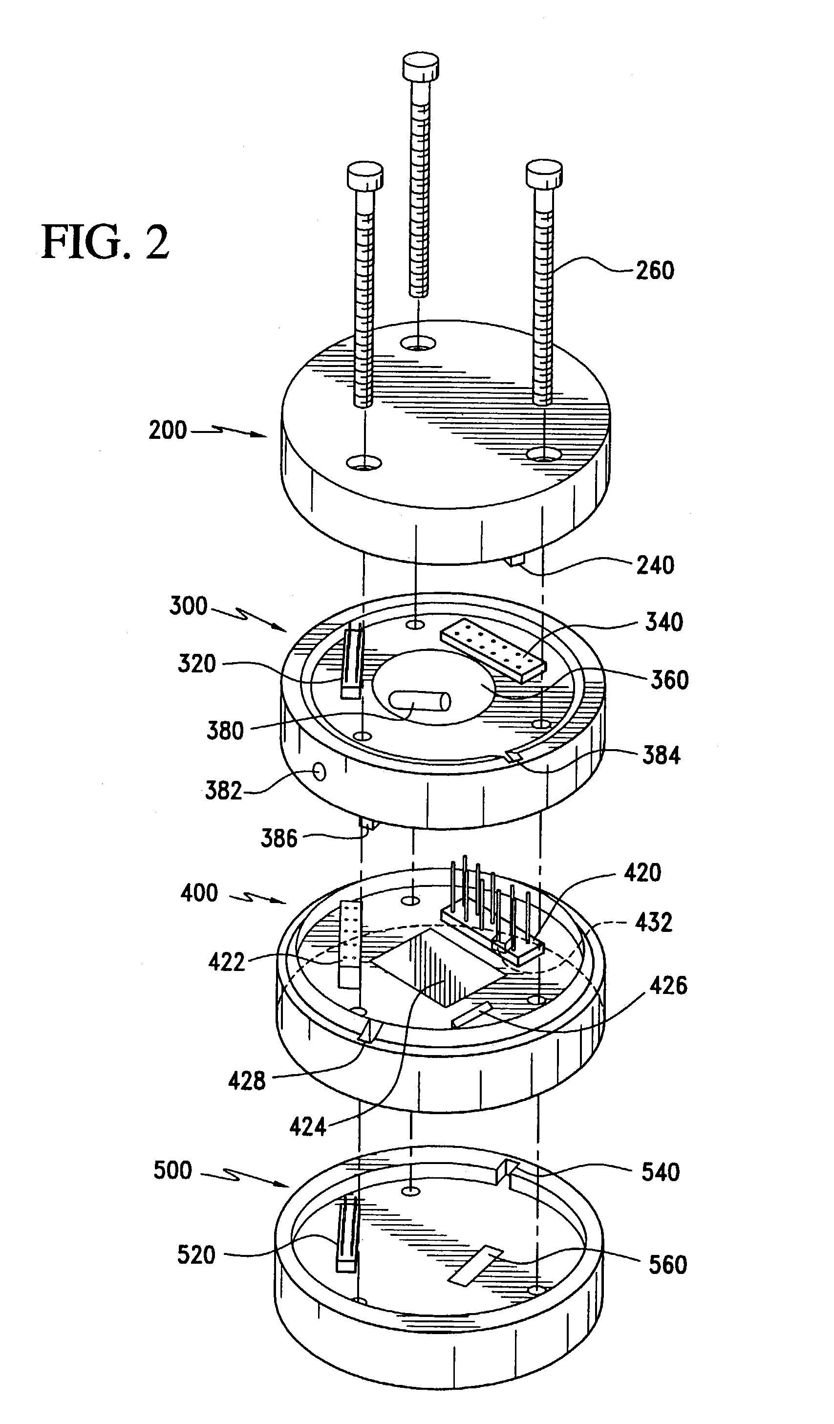
[0014]For purposes of clarification, the following table includes a list of parts for the embodiment shown in FIG. 2.

[0015]

PartNumber:Description:200Top Cover:NotInterconnect-female-TriggerShownAssembly to Top Cover240Alignment key260Machine Screws300Trigger Assembly:320Interconnect-male-TriggerAssembly to Top Cover340Interconnect-female-TimerAssembly to Trigger Assembly360Line monitoring circuit380Photo-capacitor382Mechanical safety wire hole384Alignment slot386Alignment key400Timer Assembly:420Interconnect-male-TimerAssembly to Trigger Assembly422Interconnect-female-Base toTimer Assembly424Programmable Clock Assembly426Oscillator428Alignment slot432Alignment key500Base:520Interconnect-male-Base toTimer Assembly540Alignment slot560Initiator

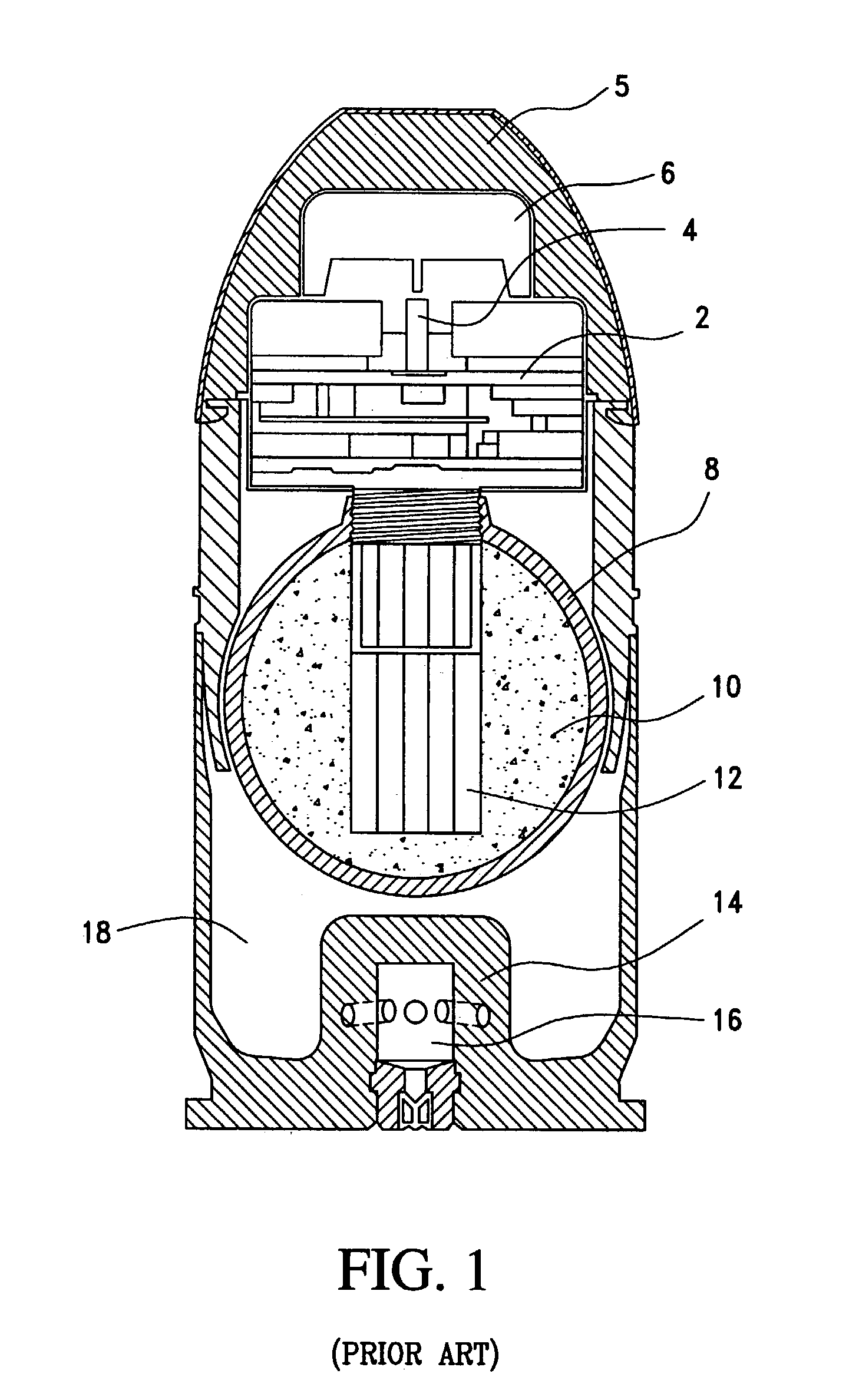
[0016]FIG. 1 shows a conventional 40 mm rifle launched grenade, for which the inventive fuze may be used. The fuze assembly 2, in a conventional 40 mm grenade occupies a substantial portion of the projectile. The pressure plate 6, strikes the imp...


PUM


Abstract

A modular fuze assembly is provided for use in multiple types of military ordnance. The fuze comprises a base unit having an initiator for arming the fuze; a timer assembly that includes a programmable clock package; a trigger assembly comprising a line monitoring circuit and a photo-capacitor; and a top cover unit. Each of the individual components are interconnected together to form a single, unitized system. Multiple initiation stages are provided to ensure payload activation.

Description

FIELD OF THE INVENTION[0001]The present invention relates to the field of fuzing systems that are used to initiate the firing of ordnance.BACKGROUND OF THE INVENTION[0002]Traditionally, fuzes used for the initiation of ordnance have relied upon a mechanical system to begin the arming process. The most complex mechanical systems are clockwork driven safety and arming systems. Such systems are activated either with inertia by using a counterweight system that is driven by rotation imparted on the munition by the rifled barrel (For example, see U.S. Pat. No. 6,145,439), or directly by an impeller such as on free fall bombs.[0003]In order for a mechanical system to be reliable, it typically must be large and physically well supported. Such requirements result in fuzes that displace more payload in “man portable weapon systems” where there exists very little room for either the fuze or the payload. For example, in the M406 (40 mm grenade), almost 50% of the projectile is composed of the ...

Claims


Application Information

Patent Timeline
IPC IPC(8): F42C11/06F42C15/40
CPCF42C11/065F42C15/40
Inventor SUTCLIFFE, SCOTT A.
Owner ENGEL BALLISTIC RES
Why Eureka
Try Eureka