Variable geometry camshaft

a variable geometry and camshaft technology, applied in the direction of valve details, valve arrangements, valve drives, etc., can solve the problems of reducing the efficiency of the engine, the number of device components, and the complexity of the material processing, so as to reduce the amount of valve lift, increase the overlap condition, and widen the range of maximum lift

Inactive Publication Date: 2007-05-08
LAKEMAN MELISSA
View PDF18 Cites 6 Cited by
  • Summary
  • Abstract
  • Description
  • Claims
  • Application Information

AI Technical Summary

Benefits of technology

[0037]The novelty of the present invention is supported by an “x” and “y” cam axis movement over an arc that is three (3) times the length of the previous invention. The movement along the cam's “x” axis alters the location of cam lobe contact on the camfollower. The “y” axis motion of the cam adjusts the space between the cam heel and the contact surface of the cam follower. The “y” axis spacing, between cam heel and contact lever, sets the rotational position where the cam lobe begins to exert a force upon the cam follower to begin the period of valve opening.
[0038]The V.G.C. uses Four-to-One (4:1) gear reduction assemblies to drive suspended dedicated cams that sweep across twenty-four degrees (24°) of arc. The drive gear turns at twice the crank speed and the reduction ratio rotates the cam at one-half (½) the crank speed. Four degrees (4°) of cam movement along the arc causes the timing of cam to cam follower contact to be retarded or advanced by one degree (1°). An asymmetrical expansion or contraction of valve opening is produced by this timing shift in cam to cam follower contact. The cam follower is mounted on a sliding tower and its motion is alig

Problems solved by technology

The expense of integrating a variable valve operation device into production will include: the total number of device components, the sophistication level of material processing, the number of labor hours for assembly, and the dimension tolerances required for the components to meet design specifications.
As the intake valve opens there is a period of lost intake duration time due to the inertia of the stationary air column entering the cylinder.
As engine speed increases to the high end of the r.p.m band

Method used


Image

  • Variable geometry camshaft
  • Variable geometry camshaft
  • Variable geometry camshaft

Examples


Embodiment Construction

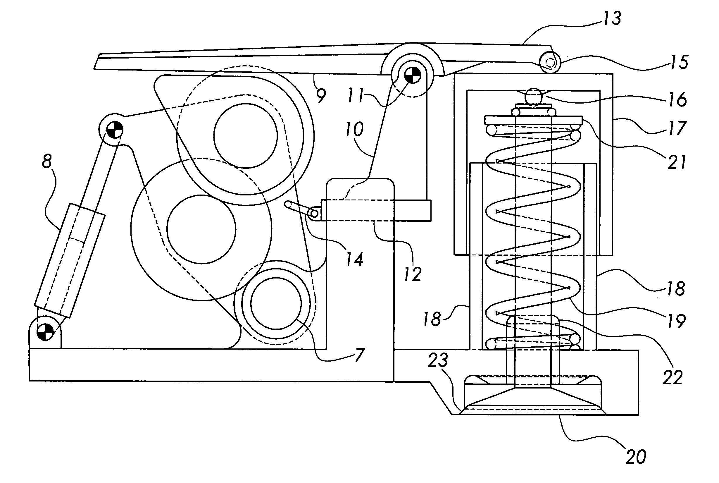
[0085]The present invention is based on the ability to control the mechanical interaction among Three (3) component sub-assemblies; 1.) a suspension bracket, camshaft, and gear reduction assembly, 2.) a camfollower contact lever, fulcrum, rocker arm, and sliding base assembly, and 3.) a valve, valve guide, valve spring, and valve piston assembly. The functions and contributions of these component sub-assemblies to the utility of the invention concept will be presented and described in the foregoing order.

Suspension Bracket, Camshaft, and Gear Reduction Assembly

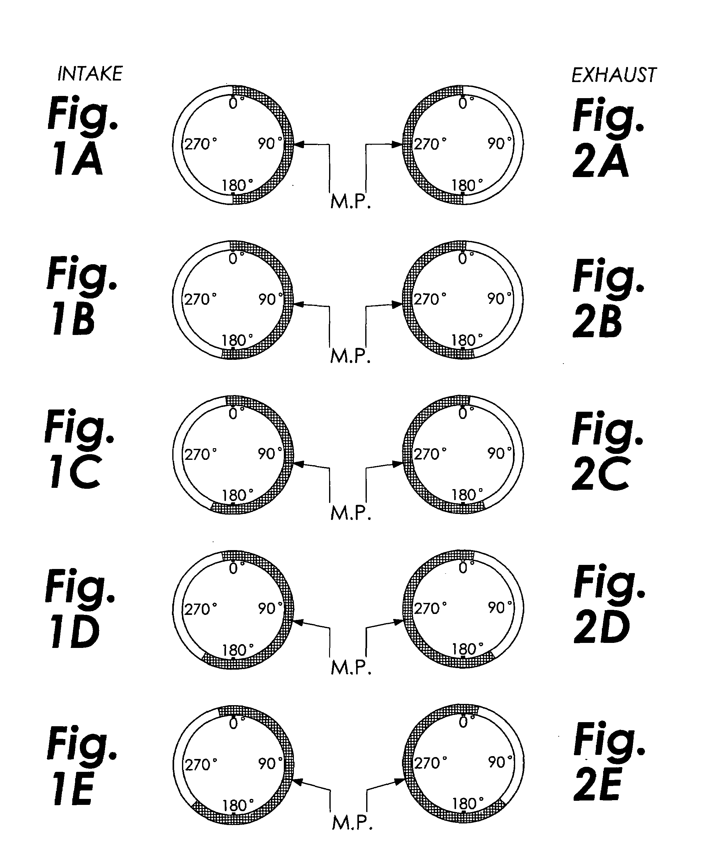
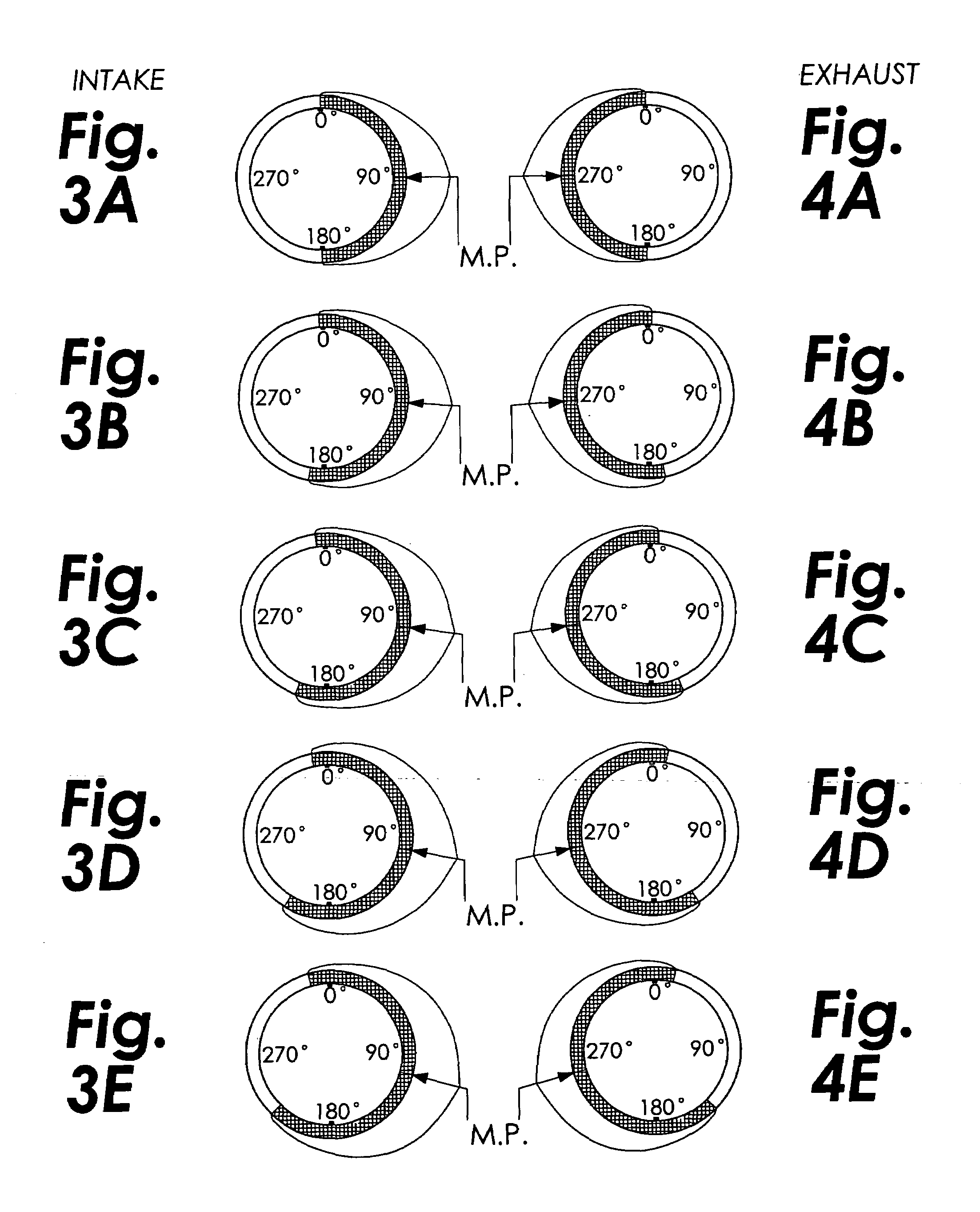
[0086]The V.G.C., or Variable Geometry Camshaft concept is based on the position of the cam axis, its contact location and its direction of engagement with a camfollower in Two (2) distinct orientations that assist either the intake or exhaust functions. FIG. 11, shows the position arrangement of components that are used for operation of the intake valve. The camshaft, 1, is housed within a suspension bracket assembly, 2, and ...


PUM


Abstract

The invention improves volumetric efficiency of the internal combustion engine. A suspended cam, 1, follows a limited arc of rotation about the axis of a drive gear, 3. A change in engine speed (r.p.m.) activates the hydraulic piston 8, and alters the cam heel position along this arc that is tangent to a cam follower, 9. The separation distance, between the cam follower and cam heel, determines the duration of valve opening. The separation distance and the rocker arm ratio control the amount of valve lift. As the cam axis sweeps across the cam follower, there is coordinated movement of the cam follower fulcrum, 11. This tempers the otherwise excessive change in rocker arm ratio as the cam contact point on the cam follower moves in the “x” direction with rotation of the suspension assembly, 2. The rotation of the cam axis and gear reduction assembly, 4, 5, &6, about the drive gear, shifts the timing of cam contact. This timing shift creates a desirable asymmetrical expansion or contraction in the duration period of valve opening.

Description

CROSS-REFERENCE TO RELATED APPLICATION(S)[0001]The present invention claims the benefit of U.S. Provisional Patent Application No. 60 / 479,621, filed 18 Jun. 2003, which is hereby incorporated by reference.TECHNICAL FIELD[0002]The present invention relates to improving volumetric efficiency of an engine, particularly, but not exclusively, to improving volumetric efficiency using a variable geometry camshaft.BACKGROUND OF THE INVENTION[0003]All variable valve lift and timing mechanisms are designed with the objective of improving volumetric efficiency. A review of the tenets of cam design is presented to identify ideal valve operation and function across a range of engine rotation speeds. This summary also identifies the inherent compromises of fixed cam lobe design that must balance engine economy with output power. Using a “gold standard”, for purposes of objective comparison, all devices that claim variable valve operation should be assessed in their ability to emulate ideal charac...

Claims


Application Information

Patent Timeline
IPC IPC(8): F01L1/34
CPCF01L1/026F01L13/0015F01L13/0063
Inventor GRIFFITHS, GARY L.
Owner LAKEMAN MELISSA
Why Eureka
Try Eureka