Vacuum assisted ply placement shoe and method

a technology of ply placement and vacuum injection, which is applied in the direction of manufacturing tools, soldering devices, auxiliaries welding devices, etc., can solve the problems of increasing the cost of composite items, increasing the cost of manufacturing composite items, and requiring correspondingly substantial support for the form, so as to facilitate proper adhesion of the plies to the substrate and sufficient force

Inactive Publication Date: 2007-05-08
THE BOEING CO
View PDF10 Cites 52 Cited by
  • Summary
  • Abstract
  • Description
  • Claims
  • Application Information

AI Technical Summary

Benefits of technology

[0007]The foregoing needs are met, to a great extent, by the present invention, wherein in one respect an apparatus and method is provided

Problems solved by technology

However, as the size of the layup increases and/or permeability of the layup decreases, the use of debulking tables tends to become undesirably expensive and cumbersome.
Another disadvantage of such known rolling presses is that a correspondingly substant

Method used


Image

  • Vacuum assisted ply placement shoe and method
  • Vacuum assisted ply placement shoe and method
  • Vacuum assisted ply placement shoe and method

Examples


Embodiment Construction

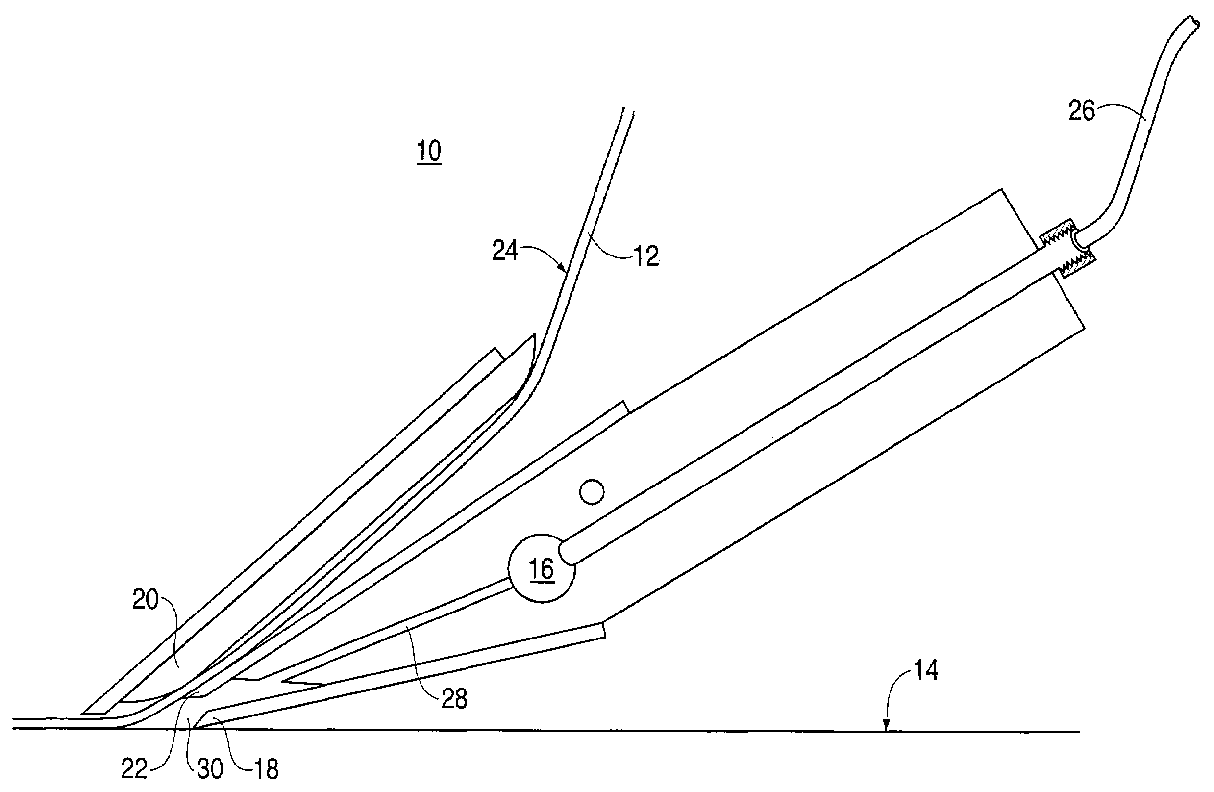
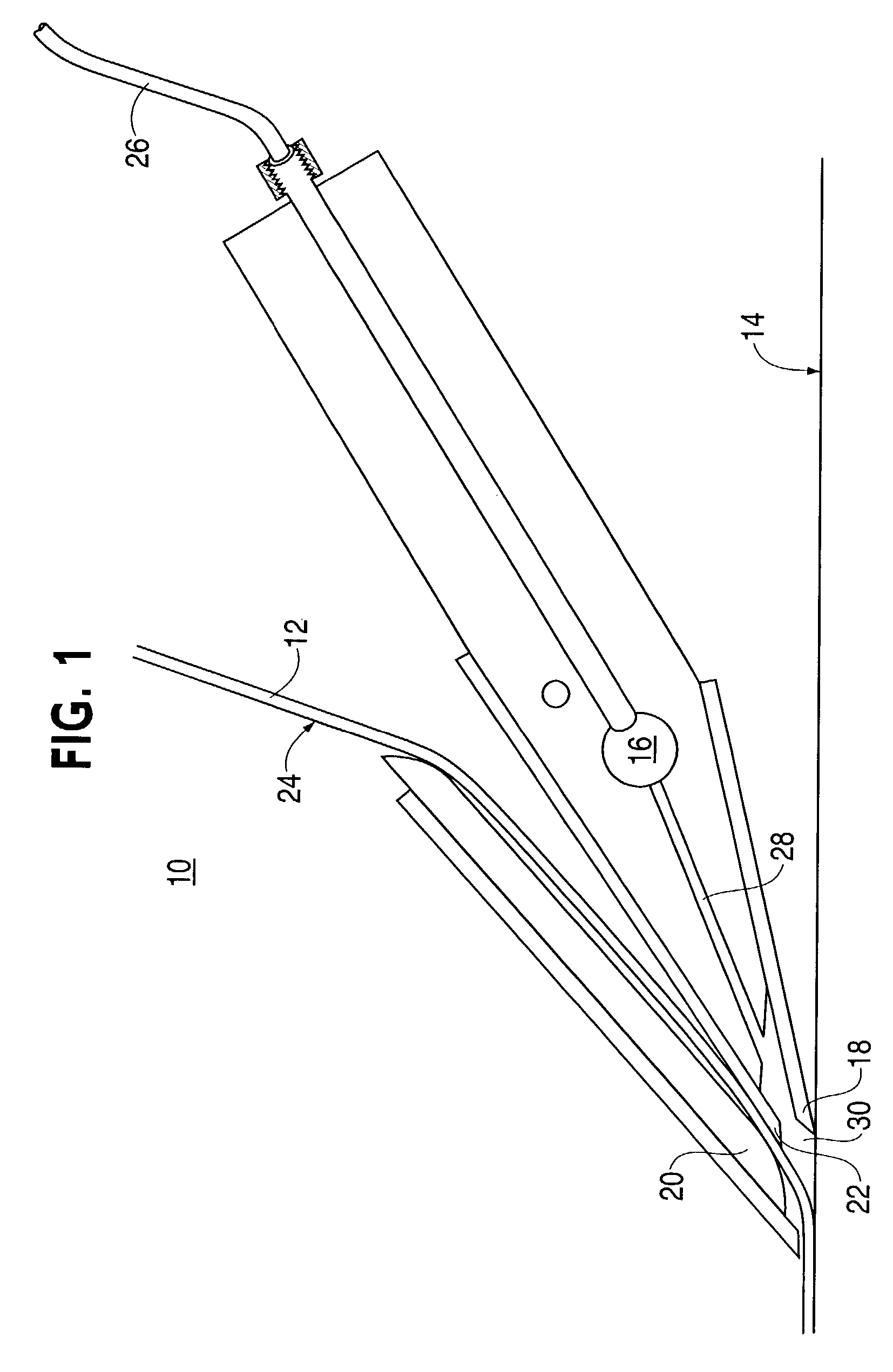
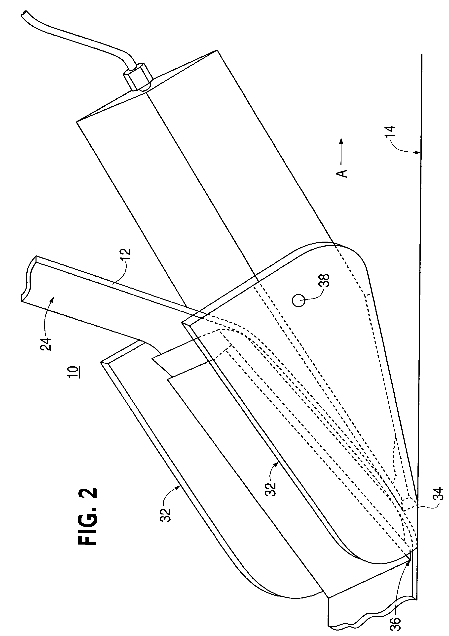
[0020]The present invention provides a ply placement device and method. In some embodiments, the ply placement device includes a vacuum manifold assembly configured for attachment to a vacuum source and a substrate seal configured to provide a substantially gas impermeable sliding interface with a substrate surface, such as the surface of a layup form, the surface of previously placed plies, and any other surface on to which the ply may be placed. The ply placement device also includes a ply seal configured to provide a substantially gas impermeable sliding interface with the ply. Vacuum applied to the vacuum manifold assembly depressurizes an area between the ply and the substrate surface.

[0021]Another embodiment in accordance with the present invention provides a method of producing a composite structure. A layup form corresponding to the composite structure and having a substrate surface configured to receive a ply is prepared. A vacuum assisted ply surface to produce the composi...


PUM

PropertyMeasurementUnit
Areaaaaaaaaaaa
Heataaaaaaaaaa

Abstract

A device for placing a ply on a substrate surface includes a vacuum manifold assembly configured for attachment to a vacuum source and a substrate seal configured to provide a substantially gas impermeable interface with the substrate surface. This device further includes a ply seal configured to provide a substantially gas impermeable interface with the ply. In this manner, vacuum applied to the vacuum manifold assembly depressurizes an area between the ply and the substrate surface.

Description

FIELD OF THE INVENTION[0001]The present invention generally relates to a ply placement device. More particularly, the present invention pertains to a vacuum assisted ply placement device.BACKGROUND OF THE INVENTION[0002]Laminated materials such as, for example, composites are widely utilized to increase structural rigidity in a wide variety of products. For example, composites are generally utilized by the airplane construction industry to build structural members of airframes. In some of the most advanced aircraft, where high strength and rigidity and low weight are extremely important, composites may account for a significant portion of the airframe as well as the external surface or skin. Typically, these composites are constructed from a plurality of layers placed over a form. These layers are often referred to as partial or full plies. For structures exceeding the available material width, each layer is typically made up of a series of strips or courses of material placed edge ...

Claims


Application Information

Patent Timeline
IPC IPC(8): B32B37/10B32B37/22B32B41/00B29C63/00B29C63/02B29C65/00B29C70/38
CPCB29C63/0091B29C66/342B29C66/4722B29C66/82661B29C70/386B29C70/388B29C70/545B29C70/086B29C63/0047B29C63/0021Y10T156/1052B29C63/024B29C2791/006B29K2105/06B29L2031/3076Y10T156/12B29C66/7212B29C65/02B29C66/1122B29K2307/04B29K2309/08B29K2277/10B29C70/38B29C65/00
Inventor LEDET, ROGER J.LAUDER, ARNOLD J.SHEWFELT, MATHEW J.
Owner THE BOEING CO
Why Eureka
Try Eureka