
Mower with lever actuated drive control

a technology of drive control and lever, which is applied in the direction of transportation and packaging, agriculture tools and machines, and non-deflectable wheel steering, etc., can solve the problem of time-consuming adjustment of the deck height of the walk behind mower, and achieve the effect of increasing the transmission ra

Inactive Publication Date: 2007-05-08
AUBURN OPERATIONS
View PDF6 Cites 41 Cited by
  • Summary
  • Abstract
  • Description
  • Claims
  • Application Information

AI Technical Summary

Benefits of technology

Enables rapid and efficient adjustment of deck height and drive speed, reducing time and effort, allowing for mowing on uneven terrain without engine shutdown and improving overall mowing efficiency by allowing operation at a second higher speed without reconfiguring the transmission settings.

Problems solved by technology

Sloped and uneven ground often requires the use of a higher deck height than level ground.
Adjustment of the deck height for walk behind mowers is time consuming.

Method used


Image

  • Mower with lever actuated drive control
  • Mower with lever actuated drive control
  • Mower with lever actuated drive control

Examples


Embodiment Construction

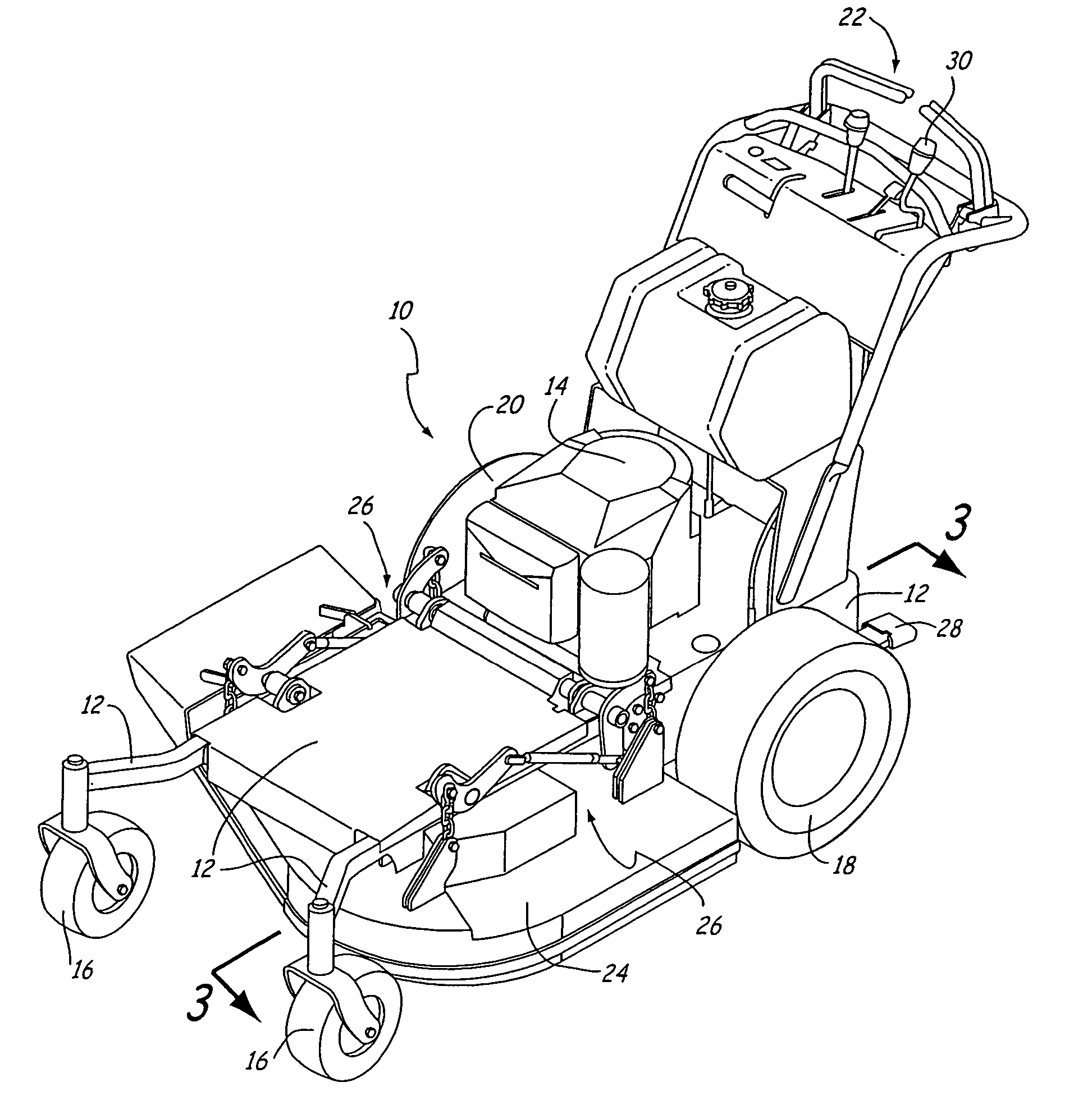
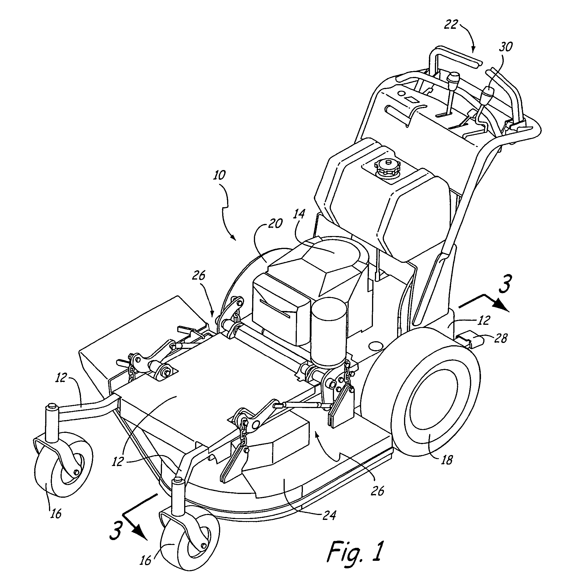
[0024]FIG. 1 is a perspective view of one embodiment of a mower of the present invention, generally referred to as mower 10. Mower 10 is a walk-behind lawn mower that provides both a rapid and efficient system for adjusting the height of deck 24 and an advantageous drive system. As illustrated in FIG. 1, mower 10 generally includes frame 12, engine 14, front wheels 16, left rear wheel 18, right rear wheel 20, handle 22, deck 24, lifting mechanism 26, and foot pedal 28. The designated left and right identifiers refer to components generally viewed from the perspective of an operator operating mower 10.

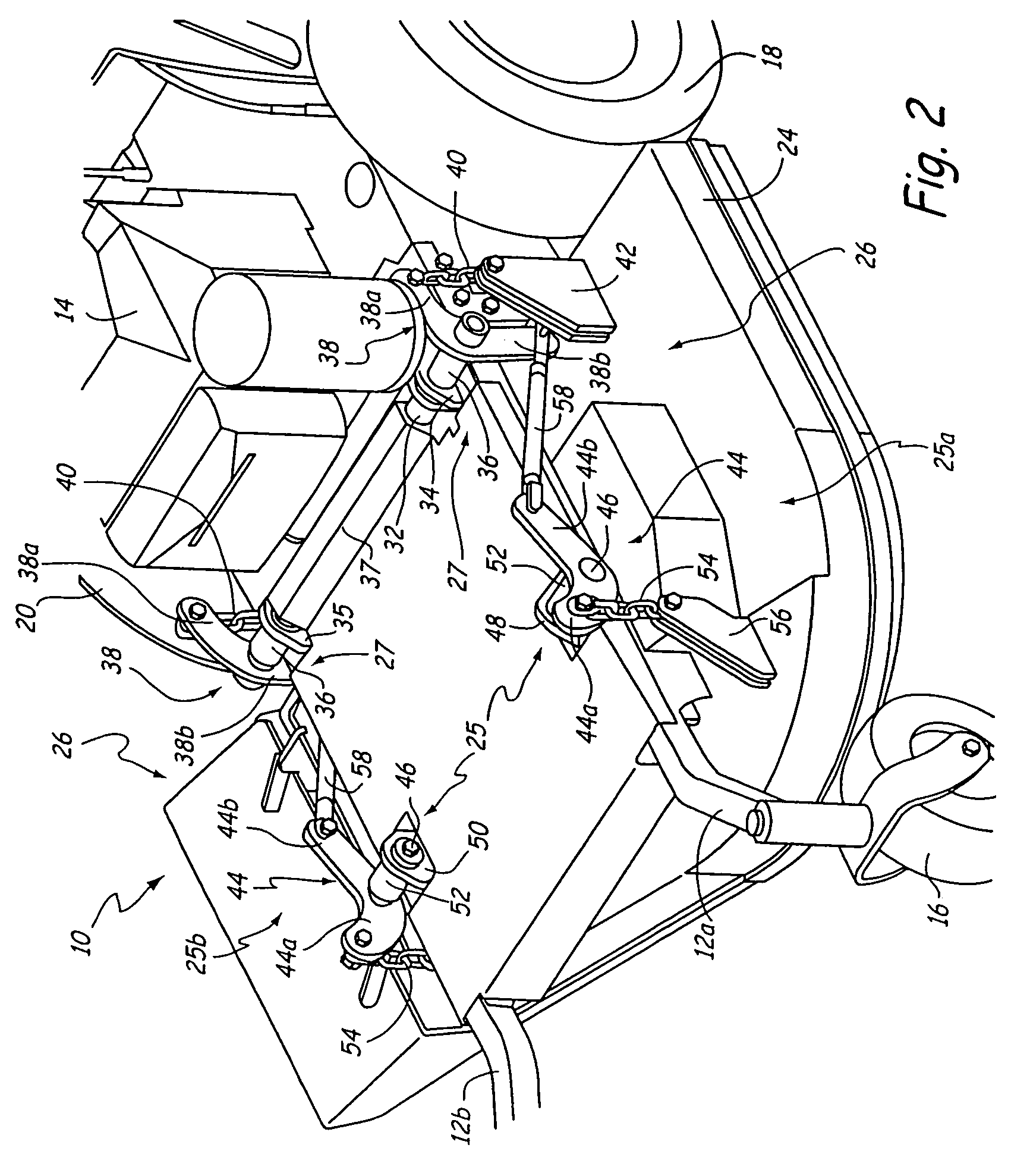
[0025]Frame 12 carries engine 14, which provides power for various mower operations, and handle 22, which supports various controls for mower 10, including a deck height setting control 30. Herein, the term “mower body” generally refers to frame 12 along mower 10, as illustrated in FIG. 1. Deck 24 is supported beneath frame 12 and houses one or more cutting blades that are driven by eng...


PUM


Abstract

A mower includes an engine-driven transmission for driving a pair of wheels at rate that varies according to the position of a transmission setting control selected by an operator. The transmission setting control positions a member that has a stop surface proximate to a transmission speed input on the transmission. The transmission speed input is adjusted by one or more levers on the mower. The transmission setting control is adjusted to define a home position of the stop surface relative to the transmission speed input and define a range of travel of the transmission speed input before it contacts the stop surface. The member is spring biased toward the home position but is moveable away from the home position. The position of the transmission speed input when it contacts the stop surface defines a first rate of travel of the transmission. An operator applies a first amount of force to the lever until the transmission speed input contacts the stop surface. The operator can apply a second greater amount of force to the lever that exceeds the spring biasing force on the member to further move the transmission speed input to define a second higher rate of travel of the transmission.

Description

CROSS-REFERENCE TO RELATED APPLICATION[0001]This Continuation Application claims priority under 35 U.S.C. § 120 to U.S. patent application Ser. No. 10 / 844,860, filed May 13, 2004, entitled “MOWER WITH LEVER ACTUATED DRIVE CONTROL” that issued as U.S. Pat. No. 7,063,177, which claims the benefit of the filing date under 35 U.S.C. § 119 of U.S. Provisional Patent Application Ser. No. 60 / 488,533, filed Jul. 18, 2003, entitled “WALK BEHIND MOWER,” both of which are incorporated herein by reference.BACKGROUND OF THE INVENTION[0002]The present invention relates to mowers with mechanisms for adjusting drive speed. In particular, the present invention relates to mowers with an independent transmission for each of two rear drive wheels.[0003]Adjustment of the deck height determines the amount of vegetation that is cut. For example, at golf courses, the fairways are mowed at a much shorter deck height than are the rough or out of bounds. It is also advantageous to be able to adjust the deck h...

Claims


Application Information

Patent Timeline
Patent Type & Authority Patents(United States)
IPC IPC(8): B62D51/04
CPCA01D34/6806A01D34/824B62D51/04A01D2034/6843A01D2101/00
Inventor CRUMLY, RYAN
Owner AUBURN OPERATIONS
Learn More