Fire engine

a technology for fire engines and utility vehicles, applied in the field of firefighting utility vehicles, can solve the problems of inconvenient manipulation, inadvertent pivoting, and detrimental to the safety of users, and achieve the effect of strong retaining force and simplified assembly

Inactive Publication Date: 2007-05-08
ROSENBAUER INT
View PDF11 Cites 34 Cited by
  • Summary
  • Abstract
  • Description
  • Claims
  • Application Information

AI Technical Summary

Benefits of technology

[0008]The surprising advantage of this solution resides in the fact that, for a cabin structure of this type consisting of a driver's cab and crew and / or equipment cab, the utility vehicle can be prepared in readiness for maintenance work to be performed on the drive and equipment units, which are often disposed under the floor, even though the requirements of utility vehicles are higher in terms of free floor space, while also providing a rapid and safe entry for the crew.
[0021]These advantageous embodiments provide protected abutting and corner connections for panels of a composite structure consisting of facing layers and intermediate layers, without any risk of the layers coming apart due to stress, in particular stress caused by vibration. Strong retaining forces and simplified assembly are also guaranteed.

Problems solved by technology

The disadvantage of such an arrangement is the inconvenient manipulation needed to detach the seal arrangement from the driver's cab and to enable the driver's cab to be pivoted.
This affords the vehicle driver effortless entry to the driver's cab, but inadvertent pivoting during entry is detrimental to the safety of the user.
Patent specification AT 406 573 B discloses a box structure for a utility vehicle, in particular a fire-fighting vehicle, in which a passageway linking the driver's cab and the box structure is provided between the driver's cab and a front-end transverse support element for the box structure lying behind, and a peripheral elastic transition and sealing element is disposed in the region of side walls of the box structure and a roof support plate, which produces a sealed connection but does not prevent various vibrations.
A transition and sealing element of this type represents a very complex system if the intention is to provide a pivotable driver's cab.

Method used


Image

  • Fire engine
  • Fire engine
  • Fire engine

Examples


Embodiment Construction

[0038]Firstly, it should be pointed out that the same parts described in the different embodiments are denoted by the same reference numbers and the same component names and the disclosures made throughout the description can be transposed in terms of meaning to the same parts bearing the same reference numbers or the same component names. Furthermore, the positions chosen for the purposes of the description, such as top, bottom, side, etc., relate to the drawing specifically being described and can be transposed in terms of meaning to a new position when another position is being described. Individual features or combinations of features from the different embodiments illustrated and described may be construed as independent inventive solutions or solutions proposed by the invention in their own right.

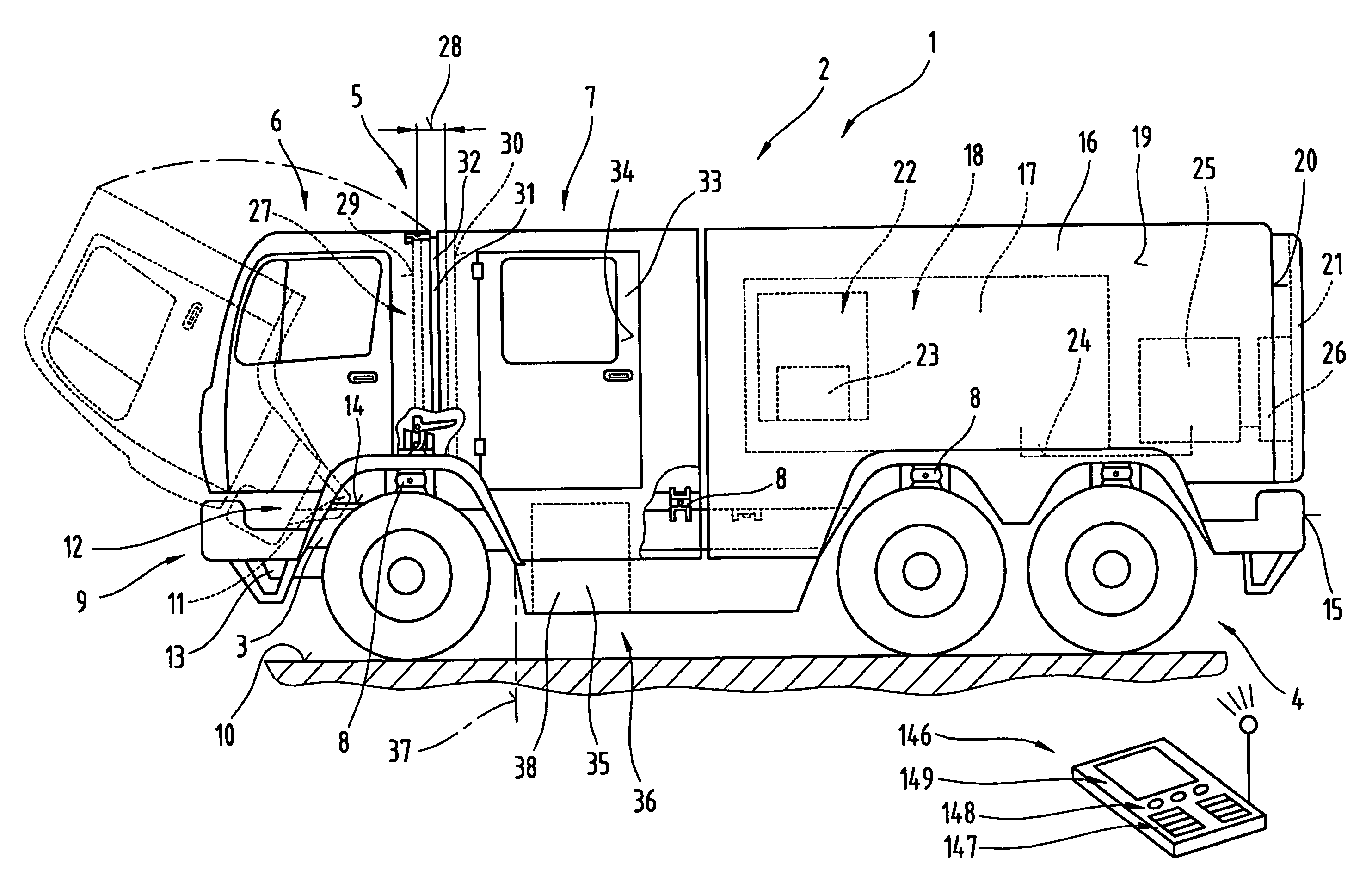
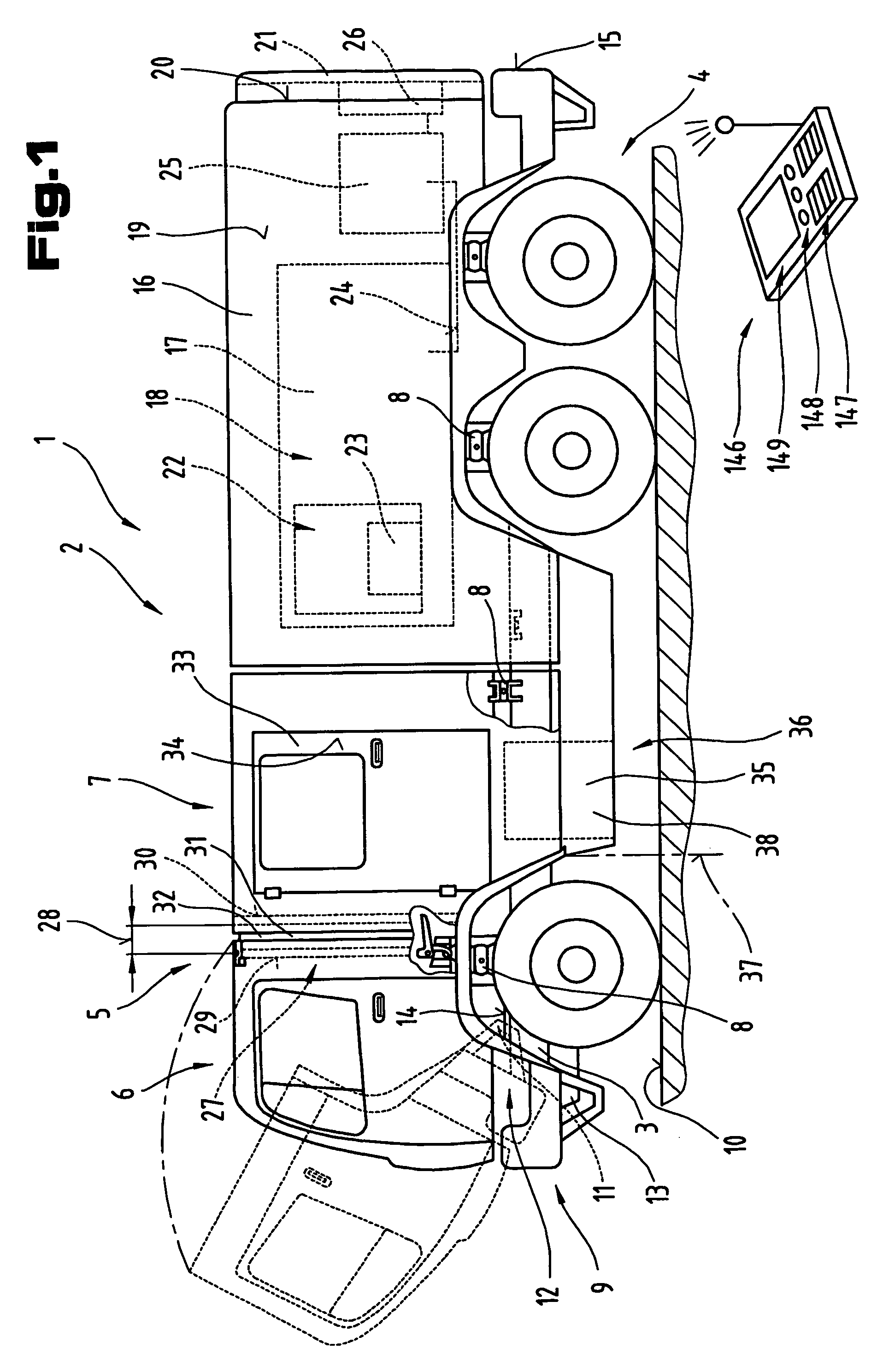
[0039]FIG. 1 shows a truck 1, in particular a fire-fighting utility vehicle 2. A double cab 5 consisting of a driver's cab 6 and a crew and / or equipment cab 7 is mounted on a chassis ...


PUM


Abstract

A truck, in particular a fire-fighting utility vehicle. The vehicle has a structure mounted on a chassis frame with a driver's cab pivotable about a horizontal axis extending transversely to the travel direction. A crew and / or equipment cab is also mounted on the chassis frame communicating with the driver's cab via a releasable connecting mechanism forming a passageway. Independently of the driver's cab and the crew and / or equipment cab, a utility structure is mounted on the chassis frame having built-in fixtures for storing tools and equipment and optionally having extinguisher units consisting of at least a tank, extinguisher pump, etc. and mounting devices are provided at entry and / or operating openings in transverse and / or longitudinal side walls of the structure.

Description

[0001]This is a U.S. National Phase application of PCT International Application Number PCT / AT02 / 00350, International Filing Date Dec. 13, 2002.FIELD OF THE INVENTION[0002]The invention relates generally to a truck and, in particular, to a fire-fighting utility vehicle.BACKGROUND OF THE INVENTION[0003]Patent specification DE 35 26 766 A1, filed by the same applicant, discloses a truck with mutually separate and independent cabs disposed at the front end of the vehicle chassis, comprising a driver's cab with all the controls needed to operate the truck and a crew and / or equipment cab immediately behind. The driver's cab, which also has seats for passengers, is linked to the crew and / or equipment cab by openings in a rear wall of the driver's cab and a front wall of the crew and / or equipment cab facing it, forming a passageway for persons. A sealing arrangement surrounding the openings provides a closure sealed off from the outside. In the region of the forward front wall, the driver'...

Claims


Application Information

Patent Timeline
Patent Type & Authority Patents(United States)
IPC IPC(8): B62D33/067A62C27/00
CPCA62C27/00B62D33/067
Inventor RONACHER, ALEXANDERHOCHDANINGER, FRANZ
Owner ROSENBAUER INT
Why Eureka
Try Eureka