Sectionalized flood control barrier

a flood control and sectional technology, applied in the direction of piers, groynes, breakwaters, etc., can solve problems such as cataclysmic damage, and achieve the effects of preventing leakage, reducing labor intensity, and being easy to handle and assembl

Inactive Publication Date: 2007-05-08
DAVIS GEORGE T
View PDF19 Cites 29 Cited by
  • Summary
  • Abstract
  • Description
  • Claims
  • Application Information

AI Technical Summary

Benefits of technology

[0013]An important object of the invention is that the barrier fills automatically from one water level to another slowly, without a sudden surge that causes many barriers to fail.
[0014]Another object of the invention is that the barrier provides stability since the weight of the water is distributed over the entire width of the barrier and the weight retains the barrier in place at any level. Since the invention disperses the weight evenly there is no tendency for the barrier to tilt, as it achieves equilibrium and is strong enough to not collapse. Since the barrier is installed on top of an existing levee the stability of the barrier is not impaired relative to sinking, as foundations for the levee are required to reach bedrock or at least deep enough to preclude descending under normal conditions.
[0015]Still another object of the invention is the ease of installation, as much of the barrier is made of light weight-plastic material which is easy to handle and assemble with a minimum of labor. Further, the barrier may be positioned directly on packed soil or on a conventional concrete footing added to the top of an existing levee. The barrier is assembled in prefabricated sections that fit together easily and are sealed with conventional waterproof material to prevent leakage.
[0016]Yet another object of the invention is the ability of the barrier to be mitered at an angle when installed to follow the contour of a levee or river bank. Since the barrier is plastic a miter saw may be used, and the proper angle is easily ascertained with the mating section simply angled in reverse.
[0017]A further object of the invention is the ability of the barrier to be prefabricated in a manufacturing facility with tooling that is easy to produce and equipment that is in present use by factories that normally make this type of product.
[0018]A final object of the invention is its ability to be shipped by standard means of transportation, as it is light-weight and modular in construction which permits loading in arrangements that are easily palletized and handled with a fork lift.

Problems solved by technology

While levees are typically constructed at a height that is sufficient to function properly under normal conditions, occasionally a severe storm causes a river to rise quickly and overflow a levee, thereby causing catastrophic damage.

Method used


Image

  • Sectionalized flood control barrier
  • Sectionalized flood control barrier
  • Sectionalized flood control barrier

Examples


Embodiment Construction

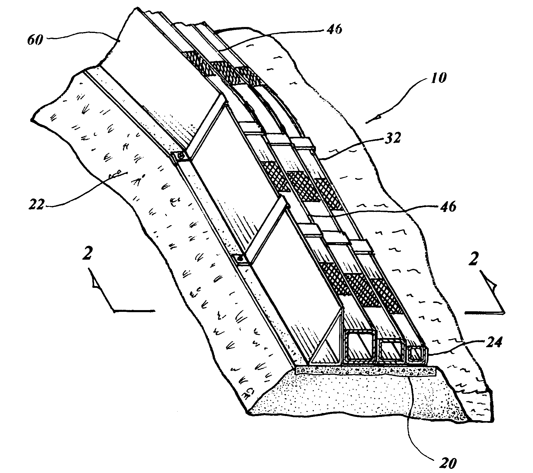
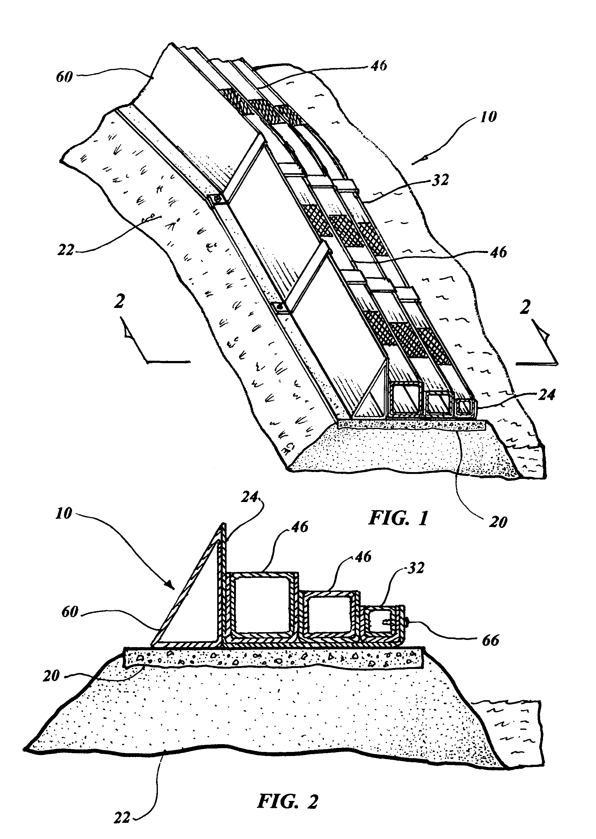
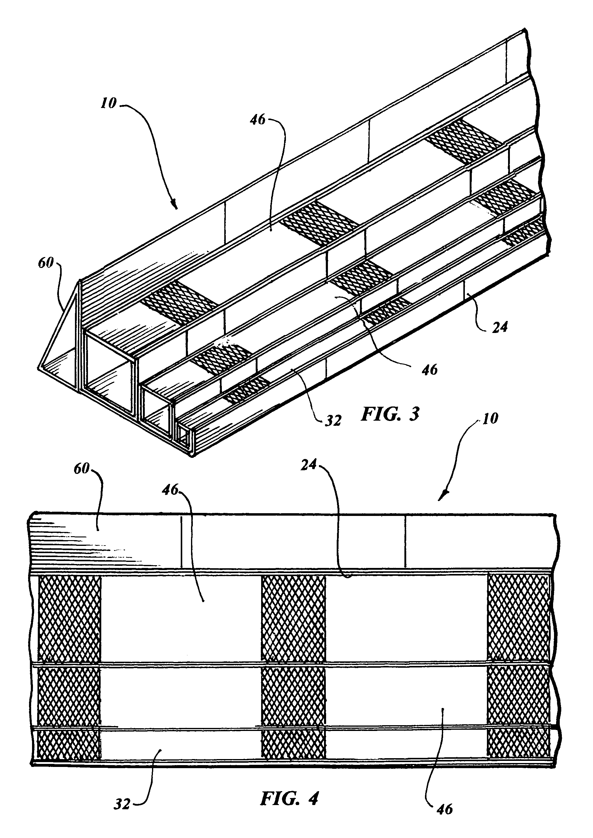
[0041]The best mode for carrying out the invention is presented in terms of a preferred embodiment for a sectionalized flood control barrier 10 that is placed on a levee or a river bank. The preferred embodiment of the barrier 10, as shown in FIGS. 1 through 21, is comprised of a footing 20 that is disposed on top of a levee 22 or adjacent to a river bank. The footing 20 includes a conventional means for attachment such as protruding studs, recessed threaded fasteners, holes for expansion bolts or the like in concrete embodiments all of which are well known in the art and therefore not illustrated in the drawings. While the footing 20 is preferably made of concrete, as illustrated in FIG. 11, sod groundwork such as depicted pictorially in FIG. 12, or compacted soil, as shown in FIG. 13, may be utilized. Both sod groundwork and compacted soil will function properly for the use intended, however the attachment means would require other well known conventional techniques such as piles,...


PUM


Abstract

A sectionalized flood control barrier (10) for mounting on top of a levee or a river bank to prevent flooding. The barrier (10) consists of a footing (20) with a series of support channels (24) that are butted end to end attached to the footing. The support shells are sealed watertight at the interface with each other and also to the footing. A series of primary channel bridge assemblies (32) and secondary channel assemblies (46) are disposed within the support channels (24) and are also butted end to end. Wind protectors (60) contiguously engage each support channel (24) and rest upon the footing for diverting the wind over the barrier. Stepped fastening risers (62) are attached to the footing on each end and over the channel assemblies, and wind protectors hold them securely in place.

Description

TECHNICAL FIELD[0001]The invention generally pertains to barriers for flood control, and more particularly to a sectionalized multi-compartment barrier that protects a body of water such as a river, from overflowing by positioning the barrier on top of existing levees, flood control areas or adjacent to river banks.BACKGROUND ART[0002]Previously, many types of barriers have been used to provide an effective means to prevent overflowing of a body of water such as a river.[0003]A search of the prior art did not disclose any patents that possess the novelty of the instant invention; however the following U.S. patents are considered related:[0004]U.S. Pat. No.InventorIssue Date4,321,774FishMar. 30, 19825,971,661Johnson et al.Oct. 26, 19995,984,576ZetzschNov. 16, 19995,993,113DarlingNov. 30, 19996,042,301SovranMar. 28, 20006,390,154HallMay 21, 2002[0005]Fish in U.S. Pat. No. 4,321,774 teaches a flood barrier consisting of a flexible membrane with a base having an end terminating in a bea...

Claims


Application Information

Patent Timeline
Patent Type & Authority Patents(United States)
IPC IPC(8): E02B7/02
CPCE02B3/102E02B3/108Y02A10/30
Inventor DAVIS, GEORGE T.
Owner DAVIS GEORGE T
Why Eureka
Try Eureka