Passive self-switching dual band array antenna

a self-switching, dual-band array technology, applied in the direction of antennas, radiating element structural forms, resonance antennas, etc., can solve the problems of insufficient coverage of both bands, inability to adequately cover both bands, and variations in dipole construction. to achieve a structure that provides both sufficient bandwidth and physical configurable within the element grid

Active Publication Date: 2007-05-08
LOCKHEED MARTIN CORP
View PDF23 Cites 54 Cited by
  • Summary
  • Abstract
  • Description
  • Claims
  • Application Information

AI Technical Summary

Problems solved by technology

With dedicated radar bands such S-Band and C-Band; C-Band and X-Band, for example, many of which are separated by nearly an octave or more of bandwidth, the selection of a radiating element becomes problematic due at least in part to difficulty in providing a suitable impedance match and element radiating pattern over both bands and the scan volume.
A single element type may be impedance matched over one frequency band or the other band, but cannot adequately cover both bands.
Moreover, variations in dipole construction have not yielded a structure that provides both sufficient bandwidth and physically configurable within an element grid of a conventional radar array.
While it is known that certain broadband elements such as notch antennas having flared or tapered notch antenna elements may be useful in forming wideband antenna arrays, dual band antenna array systems often require active switching, multiple apertures, and complex impedance matching that undesirably affect performance and usefulness of the device.

Method used


Image

  • Passive self-switching dual band array antenna
  • Passive self-switching dual band array antenna
  • Passive self-switching dual band array antenna

Examples


Embodiment Construction

[0016]It is to be understood that the figures and descriptions of the present invention have been simplified to illustrate elements that are relevant for a clear understanding, while eliminating, for the purpose of clarity, many other elements found in radar or communications systems and methods of making and using the same. Those of ordinary skill in the art may recognize that other elements and / or steps may be desirable in implementing the present invention. However, because such elements and steps are well known in the art, and because they do not facilitate a better understanding of the present invention, a discussion of such elements and steps is not provided herein. Moreover, it is to be recognized that the passive radiating antenna elements and their feed structure are reciprocal devices, behaving analogously in a receiving mode as in a transmitting mode. Thus, while the behavior of the elements and their feed structure may be described herein in the receive mode, it should b...


PUM


Abstract

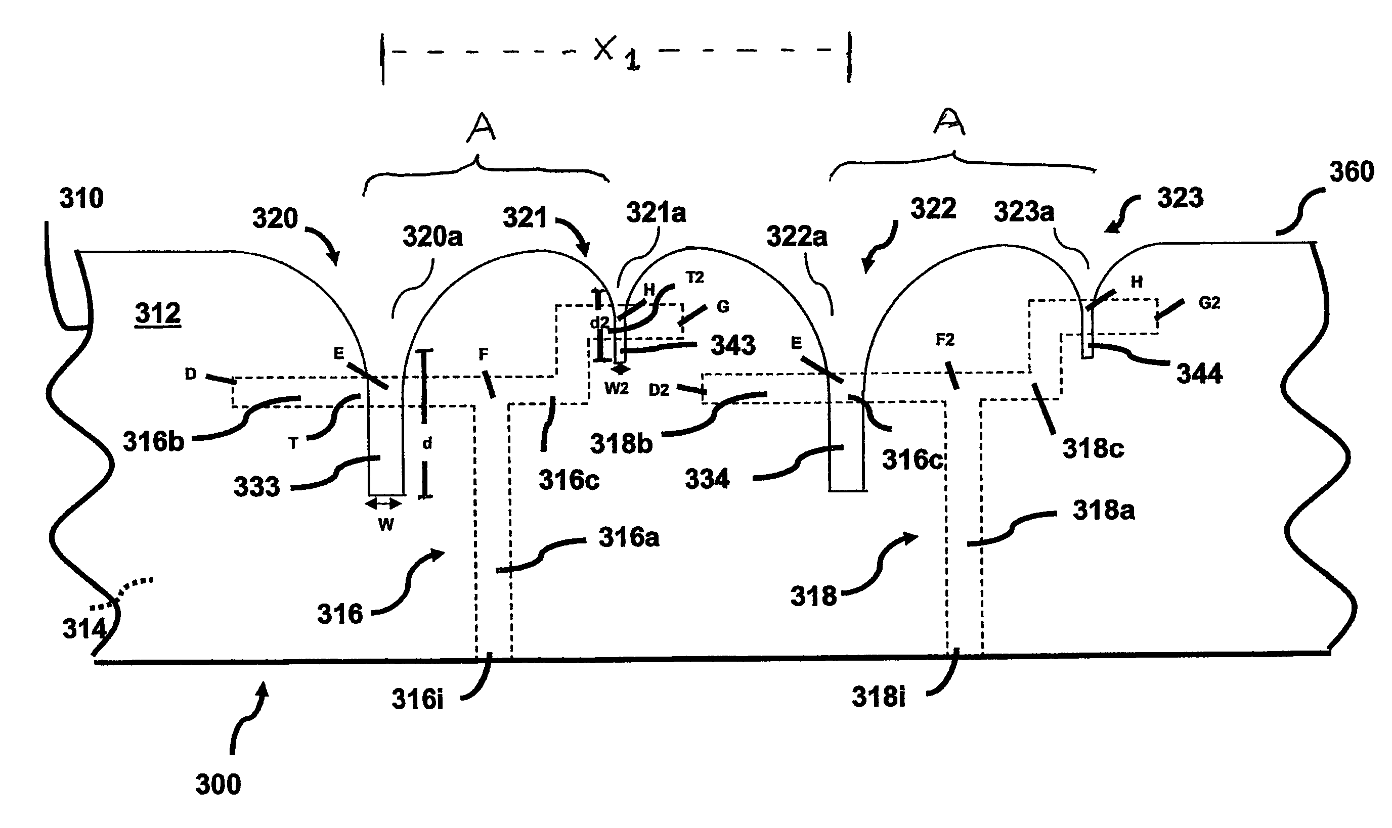
A dual band antenna array comprises a pair of coplanar antenna elements, the first antenna element excitable at a frequency within a first frequency band, the second antenna element excitable at a frequency within a second frequency band. A single transmission feed line in a second plane has an input for receiving a signal, the feed line dividing at a branch point into a first line segment for communicatively coupling the first antenna element with the input at a first feed point, and a second line segment for communicatively coupling the second antenna element with the input at a second feed point. The first and second line segments have lengths adapted for impedance matching at the first and second frequency bands, respectively, relative to the feed line input, to selectively allow energy transmission in one of the first and second line segments while reflecting energy in the other line segment according to the input signal frequency, whereby the activated antenna elements are passively switched based on the input signal frequency.

Description

FIELD OF INVENTION[0001]The present invention relates generally to antenna systems and more specifically to a dual band array antenna system.BACKGROUND[0002]Antennas are useful in a variety of data communications applications, including, for example, line-of-sight (LOS) communications applications, satellite communications (SATCOM), cellular telephony and digital personal communications systems (PCS). Antenna systems are often implemented as phased arrays of individual antennas or subarrays of antennas that are excited to cumulatively produce a transmitted electromagnetic wave that is highly directional, in order to provide a signal gain in a desired direction or to reject unwanted signals from other directions. The radiated energy from each of the individual antenna elements or subarrays is of a different phase, respectively, so that an equiphase beam front or cumulative wave front of electromagnetic energy radiating from all of the antenna elements in the array travels in a select...

Claims


Application Information

Patent Timeline
Patent Type & Authority Patents(United States)
IPC IPC(8): H01Q1/38H01Q13/10
CPCH01Q5/00H01Q5/42H01Q21/064H01Q13/085
Inventor COLLINSON, DONALD L.
Owner LOCKHEED MARTIN CORP
Why Eureka
Try Eureka