Fluorescence lifetime measurement apparatus

a fluorescence lifetime and measurement apparatus technology, applied in the direction of luminescent dosimeters, optical radiation measurement, instruments, etc., can solve the problems of difficult to reduce the error the plurality of time gates setting is inappropriately large, and the calculation of the fluorescence lifetime takes a long tim

Active Publication Date: 2007-05-08
EVIDENT CORP
View PDF5 Cites 6 Cited by
  • Summary
  • Abstract
  • Description
  • Claims
  • Application Information

AI Technical Summary

Problems solved by technology

Accordingly, the specimen must be irradiated with pulse excitation light at least several tens of thousands of times to calculate the fluorescence lifetime once, and thus it takes a very long time to calculate of the fluorescence lifetime.
However, setting a plurality of time gates inappropriately makes a large error in a calculated fluorescence lifetime.
Thus, when a fluorescence lifetime of an unknown specimen is measured in the time gates fixed, if the time gates fixed are inappropriate, it is difficult to reduce the error of the fluorescence lifetime.

Method used


Image

  • Fluorescence lifetime measurement apparatus
  • Fluorescence lifetime measurement apparatus
  • Fluorescence lifetime measurement apparatus

Examples


first embodiment

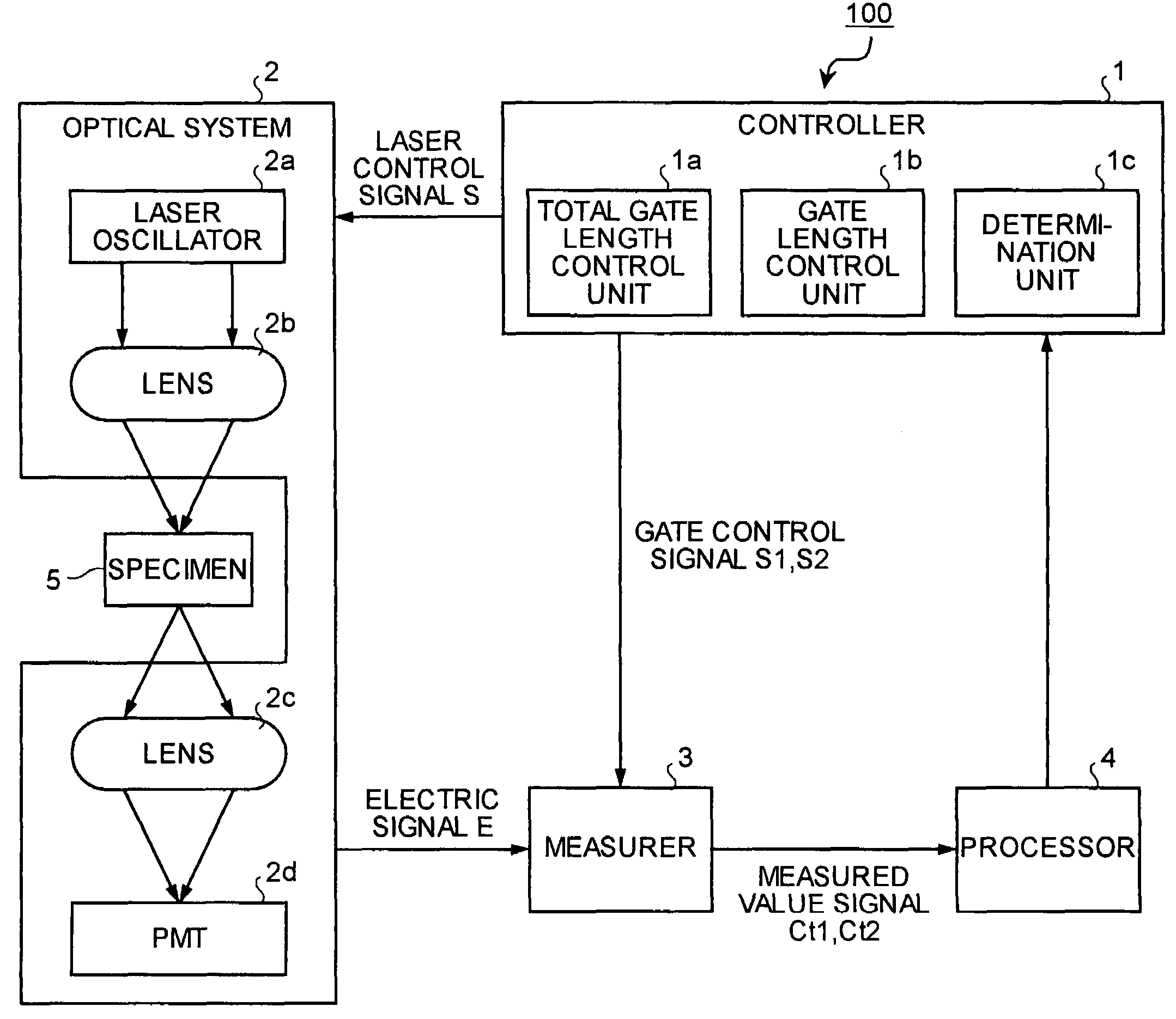
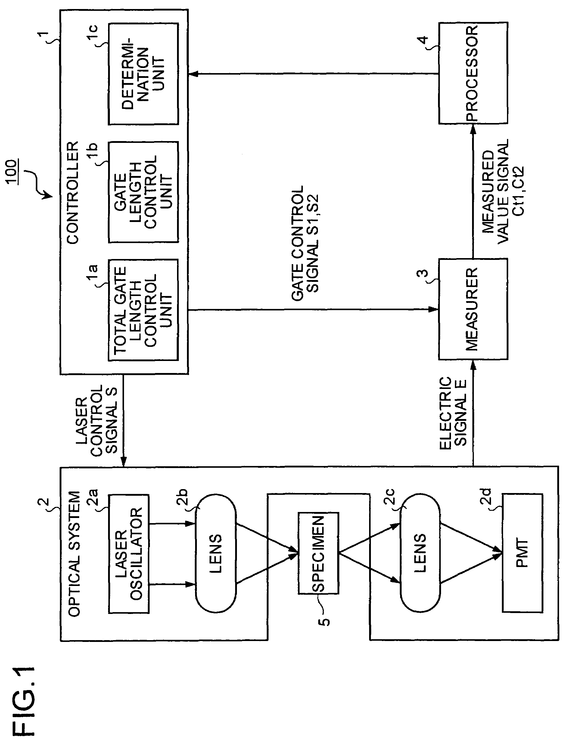
[0030]FIG. 1 is a block diagram of a fluorescence lifetime measurement apparatus 100 according to the present invention. The fluorescence lifetime measurement apparatus 100 includes a controller 1, an optical system 2, a measurer 3, and a processor 4.

[0031]The controller 1 includes a total gate length control unit 1a, a gate length control unit 1b, and a determination unit 1c. The total gate length control unit 1a controls a total gate length that is a total time window from a start to an end of measurement of the number of fluorescence photons. The gate length control unit 1b controls each gate length obtained by dividing the total gate length into a plurality of gate lengths. The determination section 1c determines whether a calculated value of a fluorescence lifetime satisfies a predetermined condition and settles the fluorescence lifetime.

[0032]The optical system 2 includes a laser oscillator 2a, lenses 2b and 2c, and a photo multiplier tube (PMT) 2d acting as a photoelectric co...

second embodiment

[0059]FIG. 13 is a block diagram a fluorescence lifetime measurement apparatus 100B according to the present invention. As shown in FIG. 13, a controller 1B includes a time delay control unit1d. The time delay control unit 1d sets gate control signals S1 and S2 such that measurement of fluorescence photons is delayed until emission of fluorescence photons becomes equal to or less than a light sensitivity of the PMT 2d.

[0060]Since an emission probability of fluorescence photons emitted from an excited specimen follows Poisson distribution, the number of fluorescence photons is maximized just after emission of the excitation light, and thus may exceed the light sensitivity of the PMT 2d. In this case, the number of fluorescence photons cannot be correctly measured, and thus a calculated fluorescence lifetime τ has a large error a. Thus, the time delay control unit 1d sets an appropriate delay time so that the number of fluorescence photons can be accurately calculated.

[0061]FIG. 14 i...

third embodiment

[0067]FIG. 16 is a block diagram of a fluorescence lifetime measurement apparatus 100C according to the As shown in FIG. 16, the measurer 3 measures the number of fluorescence photons 1i and 12 by inputting an electric signal E and outputs measured-value signals Ct1 and Ct2 to a controller 1C and the processor 4. The controller 1C determines whether a gate delay time t1 and a total gate length (t1+t2) are appropriate based on the measured-value signals Ct1 and Ct2 input thereto. When the gate delay time t1 and the total gate length (t1+t2) are not appropriate, the digital counter C1 set them again, and as long as they are appropriate, the controller 1C calculates a fluorescence lifetime τ through the processor 4.

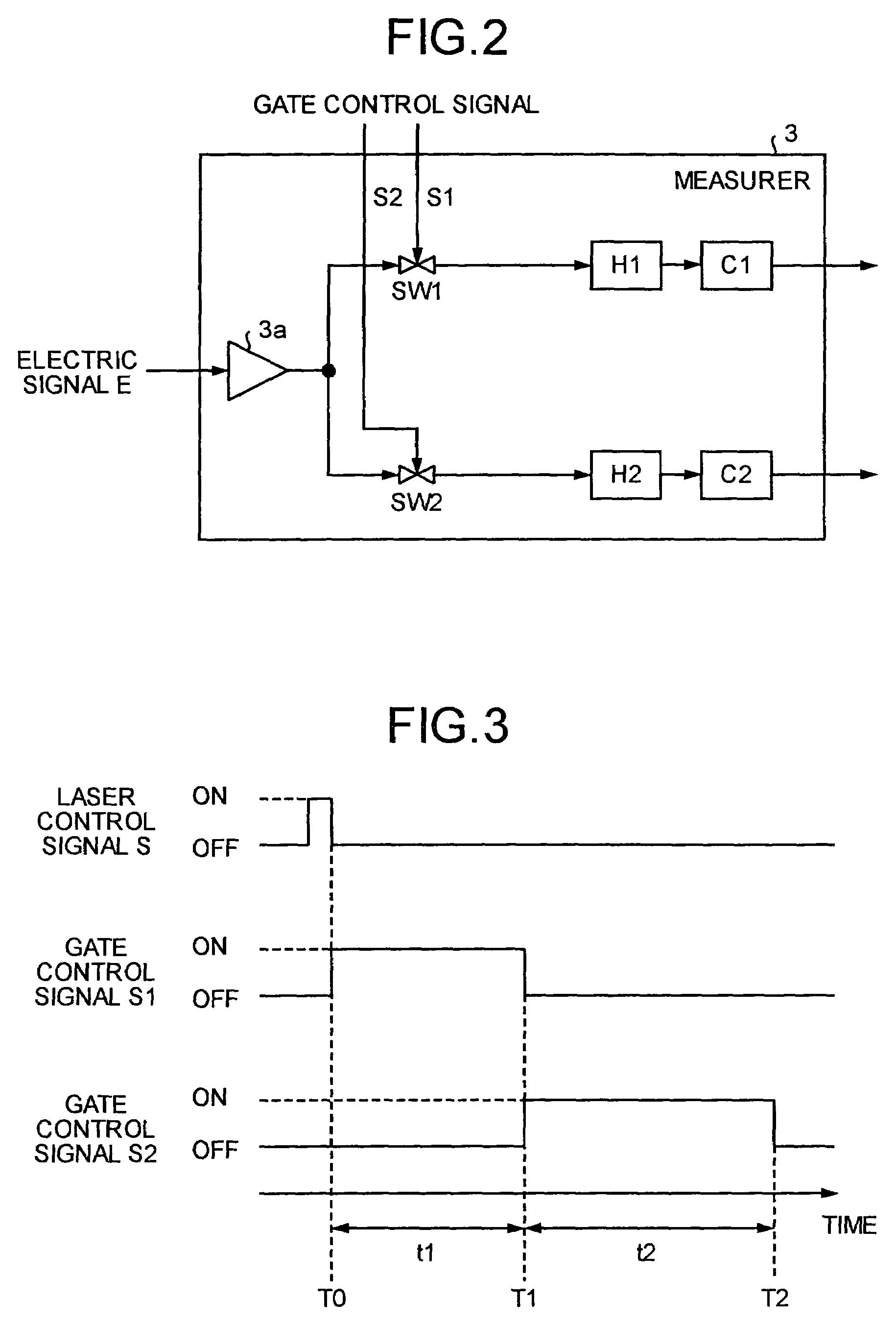
[0068]FIG. 17 shows a time chart of a laser control signal S and gate control signals S1 and S2. As shown in FIG. 17, “ON” period of times of the gate control signals S1, S2 are set to the same period of time t2, and a time difference between the time at which the first gat...


PUM

PropertyMeasurementUnit
delay timeaaaaaaaaaa
fluorescence lifetime measurementaaaaaaaaaa
lengthaaaaaaaaaa

Abstract

A fluorescence lifetime measurement apparatus includes a first controller controlling a total gate length and a second controller controlling a start gate length of a plurality of gate lengths into which the total gate length is divided. The start gate length is a time window whose start time is when measurement of the number of fluorescence photons of a specimen starts. The apparatus also includes a measurer measuring the number of fluorescence photons for each of the gate lengths; a processor calculating a fluorescence lifetime the specimen based on the start gate length and the number of fluorescence photons; and a third controller causing, when the fluorescence lifetime does not satisfy a predetermined condition, the first and second controllers to change the start gate length and the total gate length.

Description

CROSS-REFERENCE TO RELATED APPLICATIONS[0001]This application claims the benefit of priority of Japanese Patent Applications No. 2003-290445 filed on Aug. 8, 2003 and No. 2004-223466 filed on Jul. 30, 2004 the entire contents of which are incorporated herein by reference.BACKGROUND OF THE INVENTION[0002]1) Field of the Invention[0003]The present invention relates to a fluorescence lifetime measurement apparatus that calculates a fluorescence lifetime by measuring the number of fluorescence photons emitted from a specimen which is irradiated with excitation light.[0004]2) Description of the Related Art[0005]There is known a method of calculating a fluorescence lifetime by irradiating a specimen with excitation light to excite the specimen, and by measuring the number of fluorescence photons emitted from the specimen. In particular, in a field of biochemistry, attention is paid to a fluorescence lifetime measurement apparatus using pulse excitation light because a microstructure of a ...

Claims


Application Information

Patent Timeline
Patent Type & Authority Patents(United States)
IPC IPC(8): G01J3/30G01J3/44G01N21/64
CPCG01J3/4406G01N21/6408
Inventor KOTANI, TADASHI
Owner EVIDENT CORP
Why Eureka
Try Eureka