Method, system and computer program for managing energy consumption

a technology of energy consumption and computer program, applied in the direction of electric controllers, instruments, static/dynamic balance measurement, etc., can solve the problems of not always practical to forcely save energy consumption, system is often kept in operation without adjustment, wasteful energy consumption reduction, etc., to reduce the consumption and energy consumption. cost, the effect of reducing wasteful energy consumption

Inactive Publication Date: 2007-05-08
HITACHI LTD
View PDF5 Cites 169 Cited by
  • Summary
  • Abstract
  • Description
  • Claims
  • Application Information

AI Technical Summary

Benefits of technology

[0006]The system described above is able to provide the operational plan for a facility, by which the system can control the facility under a balance between amenity and cost as a result of prioritizing a reduction in wasteful energy consumption so as to efficiently decrease consumption and cost of energy.

Problems solved by technology

However, most systems, which measure energy consumption and store it in order to graphically visualize it on a web such as an intranet, have not yet been so developed as to include automatic data analysis and controlling of the building.
Furthermore, because it requires experience and labor to analyze the data of the energy management system so as to make an appropriate adjustment for controlling of the units, unfortunately the system is often kept in operation without adjustment, under the initial setting being left as is.
However, it is not always practical to forcefully save the energy consumption in order that the bill may not exceed the required cost.
There is a type of energy consumption which does not allow a reduction.
Also it is sometimes necessary to evaluate a trade-off between amenity and cost.

Method used


Image

  • Method, system and computer program for managing energy consumption
  • Method, system and computer program for managing energy consumption
  • Method, system and computer program for managing energy consumption

Examples


second embodiment

b. Second Embodiment

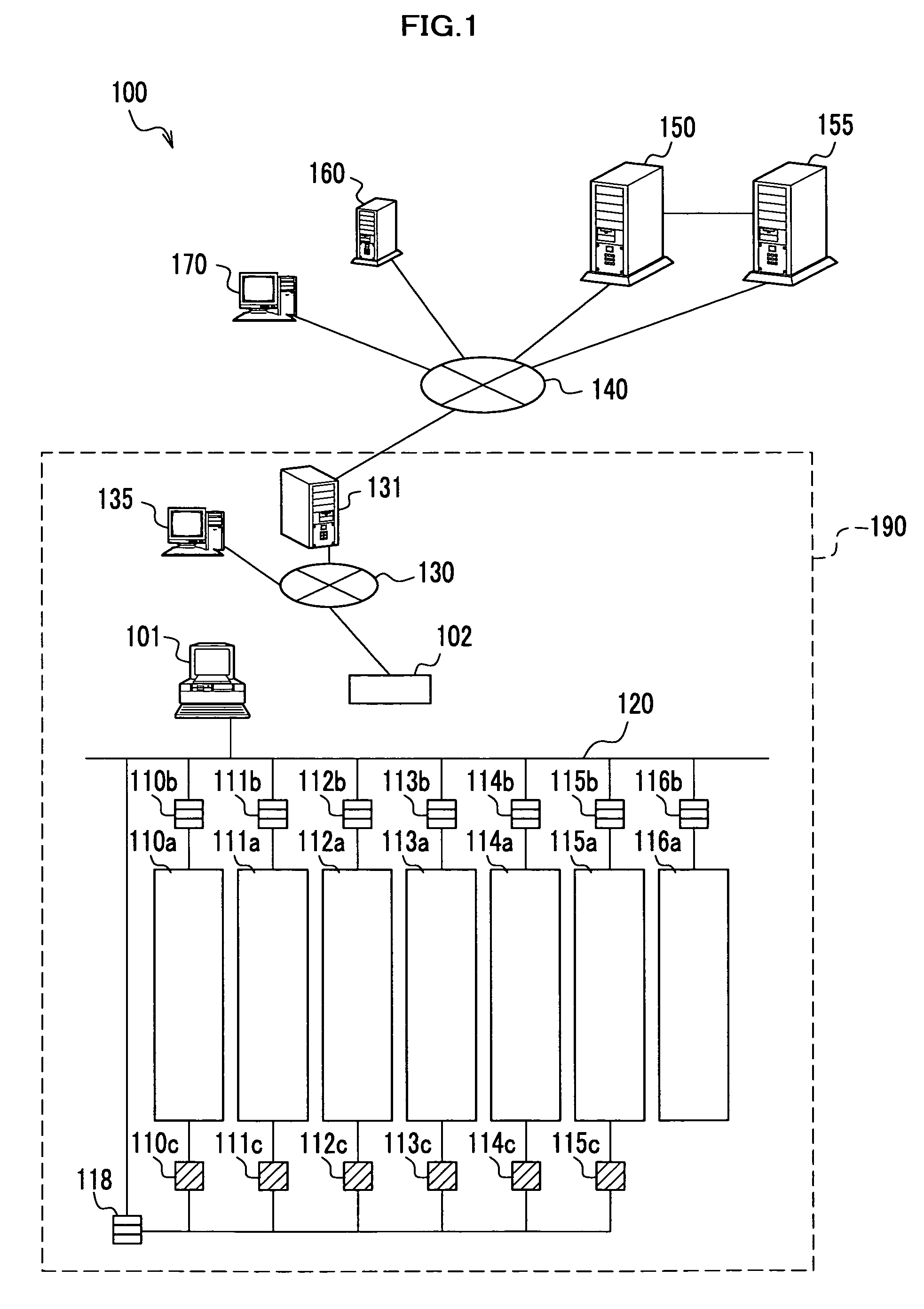
[0231]In addition to FIG. 1, another structure of units which supply a service according to the present invention may be possible. In this example, an intranet for OA system and a BA communication line are completely separated. A PC operational information server 1836 gathers PC operational information every 10 minutes, sending it to a remote control server 150 and a BA server 102. A dedicated fire wall 1803 exists between the BA server 102 and an internet. When a web site is used in order to send a sensible environment report, the report is sent to the BA server 102 while the remote control server 150 serves as a web server.

[0232]It may be possible for the BA server 102 to include the function which the BEMS center module 101 carries out in the embodiment as shown in FIG. 1 according to the present invention. Both in FIGS. 1 and 18, when an operational plan is not remotely generated but is generated in a local environment, namely within a building, the BA server...

third embodiment

c. Third Embodiment

[0235]It may be possible to install a computer program in a PC, which makes the PC to execute the processes described above, so that the PC may serve as the BA server and the BEMS center module.


PUM


Abstract

A system for managing energy consumption has a data storage module, a calculation module and an operation planning module. The data storage module stores an operational past record of a unit belonging to a facility to be managed by the system. The calculation module calculates wasteful energy consumption for the unit based on the operational past record stored in the data storage module. The operation planning module generates an operational plan for the unit belonging to the facility based on the wasteful energy consumption calculated by the calculation module.

Description

BACKGROUND OF THE INVENTION[0001]The present invention relates to a method, a system and a computer program for managing the energy consumed by units of a facility such as a building based on an operational plan generated by the system.[0002]Introduction of an energy management system into a building has been in great demand, which may result in a reduction in its energy consumption. However, most systems, which measure energy consumption and store it in order to graphically visualize it on a web such as an intranet, have not yet been so developed as to include automatic data analysis and controlling of the building. It has not been widely practiced to conduct external control for the units of a facility so as to reduce energy consumption, namely cost. Instead, it has been common that a person in charge of the facility manually controls them. Furthermore, because it requires experience and labor to analyze the data of the energy management system so as to make an appropriate adjustm...

Claims


Application Information

Patent Timeline
Patent Type & Authority Patents(United States)
IPC IPC(8): G05D23/00G05D1/00H02J3/00
CPCH02J3/00H02J2003/007Y04S40/22Y02E60/76H02J2203/20Y02E60/00Y04S40/20
Inventor MATSUBARA, MASAHIROHARADA, YASUSHISATO, YASUOKOBAYASHI, NOBUHISAYAMADA, JUNICHI
Owner HITACHI LTD
Why Eureka
Try Eureka