
Cooling structure of cylinder block

Inactive Publication Date: 2007-05-15
TOYOTA JIDOSHA KK +1
View PDF19 Cites 19 Cited by
  • Summary
  • Abstract
  • Description
  • Claims
  • Application Information

AI Technical Summary

Benefits of technology

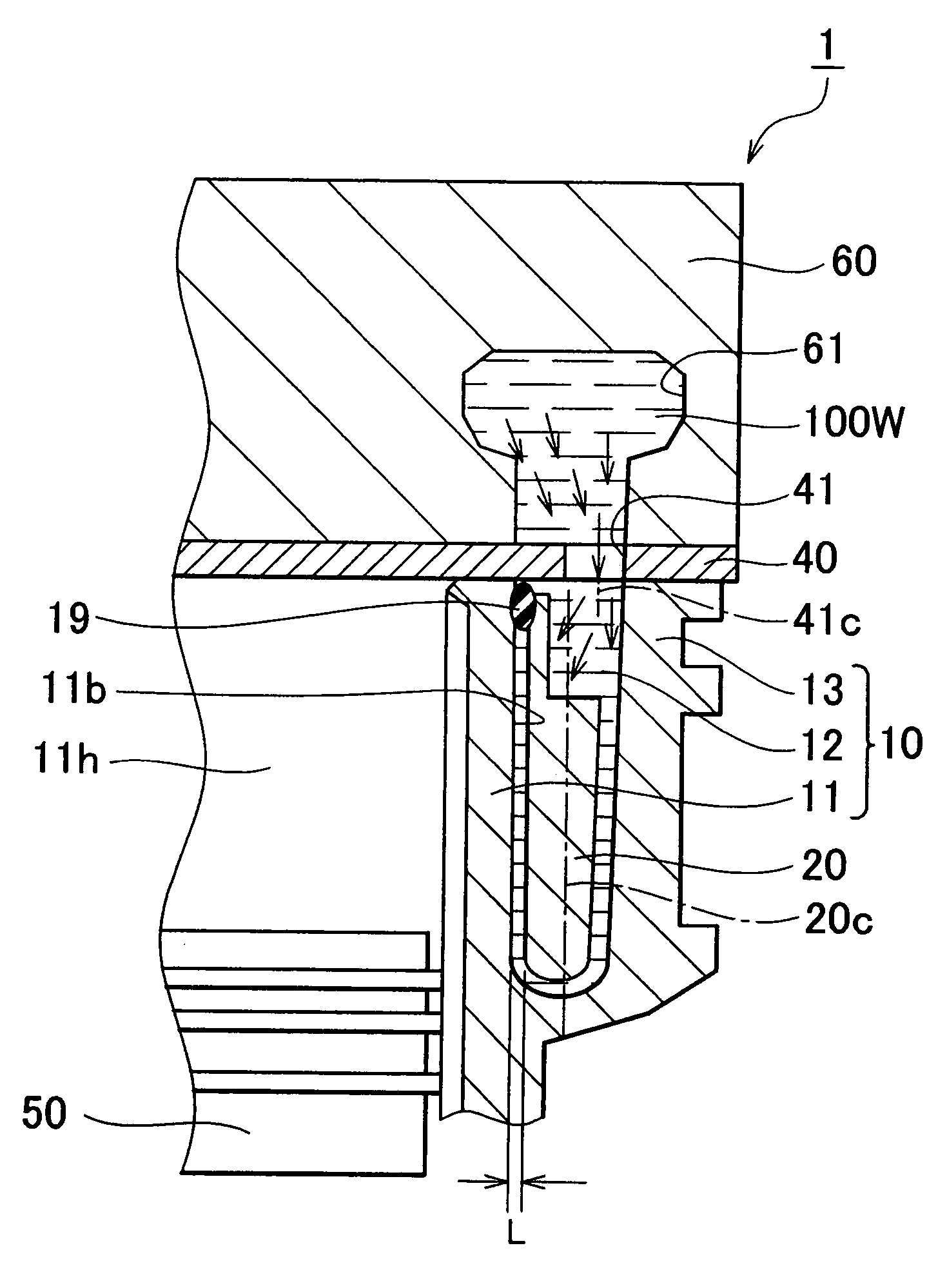
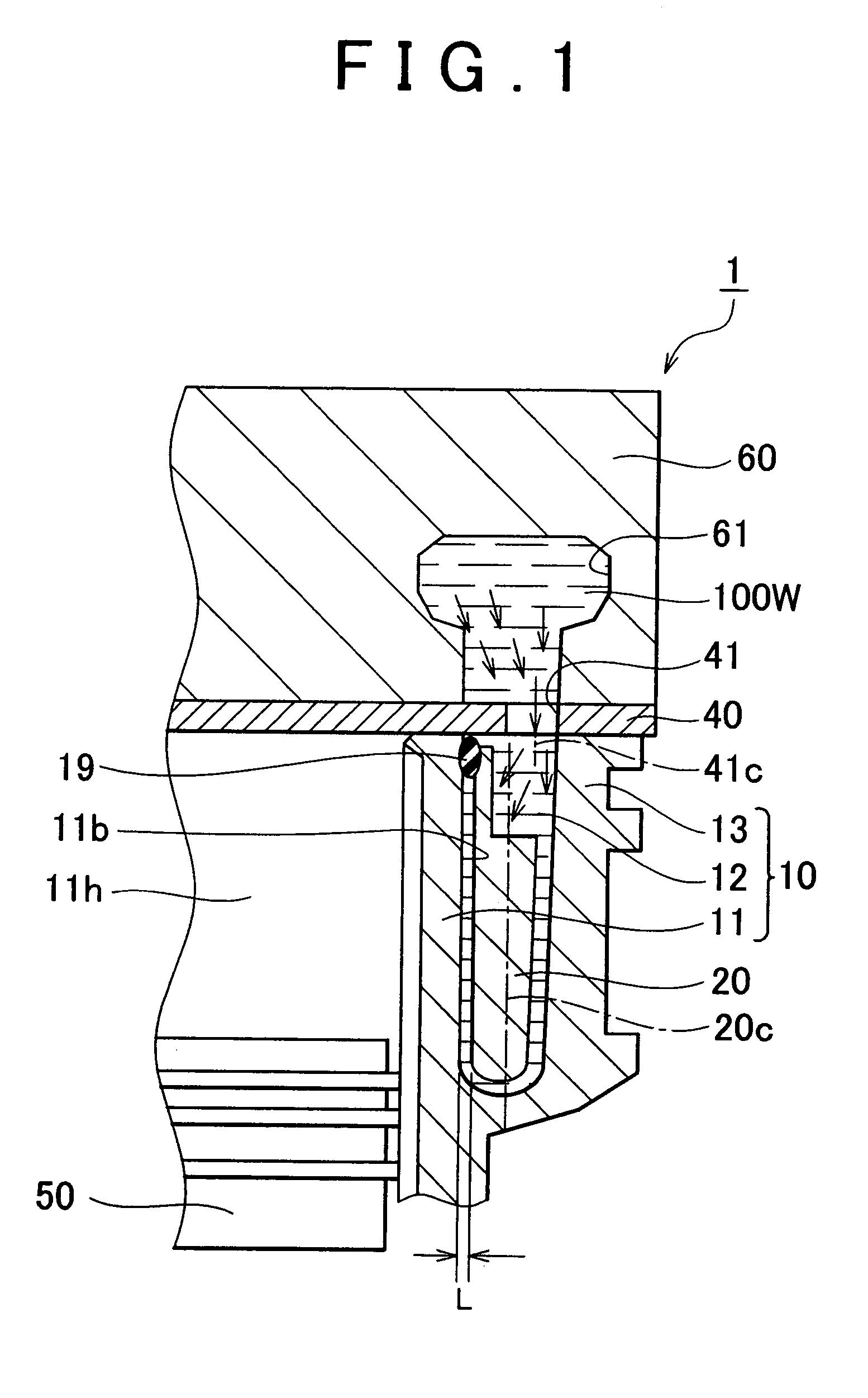
[0008]In view of the above, it is an object of the invention to provide a cooling structure of a cylinder block which makes it possible to uniformly cool the cylinder block.
[0010]In the aforementioned cooling structure of a cylinder block, the distance between the center of the hole (coolant hole) formed in the gasket and the outer periphery of the cylinder block is shorter than the distance between the center of the water jacket spacer in the thickness direction and the outer periphery of the cylinder block. Therefore, for example, when the cooling medium flows from an engine head portion into the water jacket portion of the cylinder block through the hole of the gasket, the cooling medium flows into a space between the water jacket spacer and a side opposite to the bore wall. Thus, this cooling structure is effective for preventing overcooling of the bore wall. Accordingly, the cylinder block can be uniformly cooled.
[0012]In the aforementioned cooling structure of a cylinder block, since the flow rate control mechanism is provided in the vicinity of the bypass passage, it is possible to reduce the flow rate of the cooling medium flowing along a surface of the water jacket portion on the bore wall side. As a result, the bore wall can be prevented from being overcooled, and the cylinder block can be uniformly cooled.

Problems solved by technology

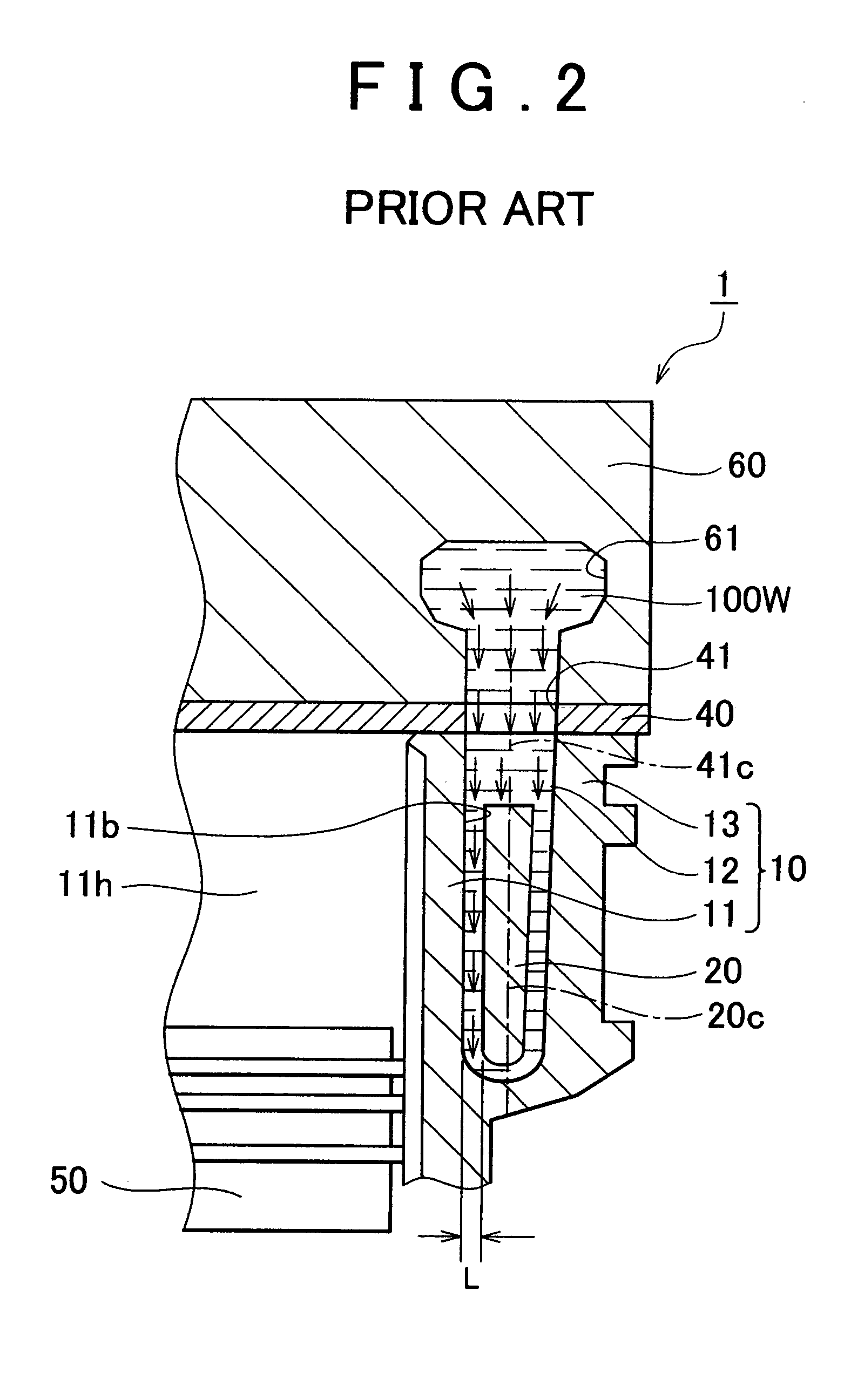
However, the bore wall is overcooled in the vicinity of a coolant hole of a head gasket, and in the vicinity of portions connected to bypass pipes (e.g., an oil cooler, an automatic transmission fluid cooler, and a turbo cooler).
Accordingly, in the conventional cooling structure of a cylinder block, it is difficult to uniformly cool the bore wall.

Method used


Image

  • Cooling structure of cylinder block
  • Cooling structure of cylinder block
  • Cooling structure of cylinder block

Examples


first embodiment

[0041]FIG. 3 is a cross sectional view showing the cooling structure of a cylinder block according to the invention. As shown in FIG. 3, since the hole 41 of the gasket 40 is formed close to the outer periphery of the cylinder block 10, the coolant flows in the outer portion of the water jacket portion 12 as shown by arrows. Thus, it is possible to suppress the flow of the coolant in the space between the water jacket spacer 20 and the bore wall 11b. As a result, the bore wall 11b can be prevented from being overcooled.

[0042]FIG. 4 is a cross sectional view showing the cooling structure of a cylinder block according to the comparative example. As shown in FIG. 4, since the position of the center 41c of the hole 41 overlaps with the position of the center 20c of the water jacket spacer 20 when seen from above, the coolant is likely to flow into the space between the water jacket spacer 20 and the bore wall 11b. Thus, an active flow of the coolant occurs in the space between the bore ...

second embodiment

[0044]FIG. 5 is a plan view showing a cooling structure of a cylinder block according to the invention. FIG. 6 is a cross sectional view taken along line VI—VI in FIG. 5. FIG. 7 is a front view showing the water jacket spacer seen in a direction shown by an arrow VII in FIG. 6. As shown in FIG. 5, after the coolant flows into the cylinder block 10 in a direction shown by an arrow 101, the coolant flows in the water jacket portion 12, and removes heat of the cylinder liner assembly 11. Then, the coolant flows out through a bypass passage 14. After the coolant flows out through the bypass passage 14, the coolant flows into equipment 200 in FIG. 6, as shown by an arrow 102. The equipment 200 includes an oil cooler, an automatic transmission fluid cooler (ATF cooler), and a turbo cooler. Thus, after the coolant flows out of the cylinder block 10 in the direction shown by the arrow 102, the coolant flows into the equipment 200 including the oil cooler, the ATF cooler, and the turbo coole...


PUM


Abstract

A cooling structure of a cylinder block includes a water jacket portion which is provided so as to surround an entire outer periphery of the bore wall; a water jacket spacer which is inserted in the water jacket portion; and a gasket which is provided in an upper portion of the cylinder block, and which includes a hole leading to the water jacket portion. The water jacket portion is supplied with coolant. A distance between a center of the hole and an outer periphery of the cylinder block is shorter than a distance between a center of the water jacket spacer in a thickness direction and the outer periphery of the cylinder block. In the cooling structure, the cylinder block can be uniformly cooled.

Description

[0001]The disclosure of Japanese Patent Application No. 2004-067871 filed on Mar. 10, 2004, including the specification, drawings and abstract is incorporated herein by reference in its entirety.BACKGROUND OF THE INVENTION[0002]1. Field of the Invention[0003]The invention relates to a cooling structure of a cylinder block, and more particularly to a cooling structure of a cylinder block which makes it possible to uniformly cool a bore wall of the cylinder block.[0004]2. Description of the Related Art[0005]A conventional cooling structure of a cylinder block is disclosed, for example, in Japanese Patent Laid-Open Publication No. 2002-30989.[0006]The Japanese Patent Laid-Open Publication No. 2002-30989 discloses a technology in which the temperature of a bore wall is made uniform by providing a water jacket spacer inside a water jacket of a cylinder block of an internal combustion engine. However, the bore wall is overcooled in the vicinity of a coolant hole of a head gasket, and in t...

Claims


Application Information

Patent Timeline
IPC IPC(8): F02F1/10F02F1/14F01P3/02F01P3/04F02F1/36F02F11/00
CPCF02F1/14
Inventor MATSUTANI, TAKASHINAKADA, TAKANORISHINPO, YOSHIKAZUHATANO, MAKOTOKUBOTA, TAKASHI
Owner TOYOTA JIDOSHA KK
Learn More