Screen system

a screen and basket technology, applied in the direction of screening, vibratory screen apparatus, gravity filter, etc., can solve the problems of poor sealing between the screen and the basket, the screen is easily damaged, and the vibratory screen is easily damaged

Inactive Publication Date: 2007-05-15
NAT OILWELL VARCO UK
View PDF8 Cites 85 Cited by
  • Summary
  • Abstract
  • Description
  • Claims
  • Application Information

AI Technical Summary

Benefits of technology

[0009]It is an object of the present invention to ...

Problems solved by technology

Hook strip screens have a number of disadvantages including the complex and time consuming mounting of the screen members in the basket, which results in significant downtime of the vibratory screen apparatus and requires the use of multiple parts.
Attaining the correct screen tension for the material to be sieved also involves intricate fine tuning and the screens are easily damaged if too much force is applied when tightening the bolts or loading means to tension the screens.
A further disadvantage is the relatively poor sealing between the screen and basket.
The metal on metal seal often results in leakage with unscreened material passing through gaps between the screen and the basket, and mixing with already screened material below the mesh screen.
Attempts to overcome the poor seal by placing rubber strips or gaskets at the metal/metal interfaces have proved unsatisfactory.
These require intricate and time consuming fitting and frequently work loose during vibration and become lost or lodged in the vibratory machine, obstructing and damaging the machinery.
In addition applying tension to the screen when tightening the tension bolt or loading means gives rise to additional stresses over and above those already suffered by the machine framework due to the vibratory motion, thereby possibly resulting in...

Method used


Image

  • Screen system
  • Screen system
  • Screen system

Examples


Embodiment Construction

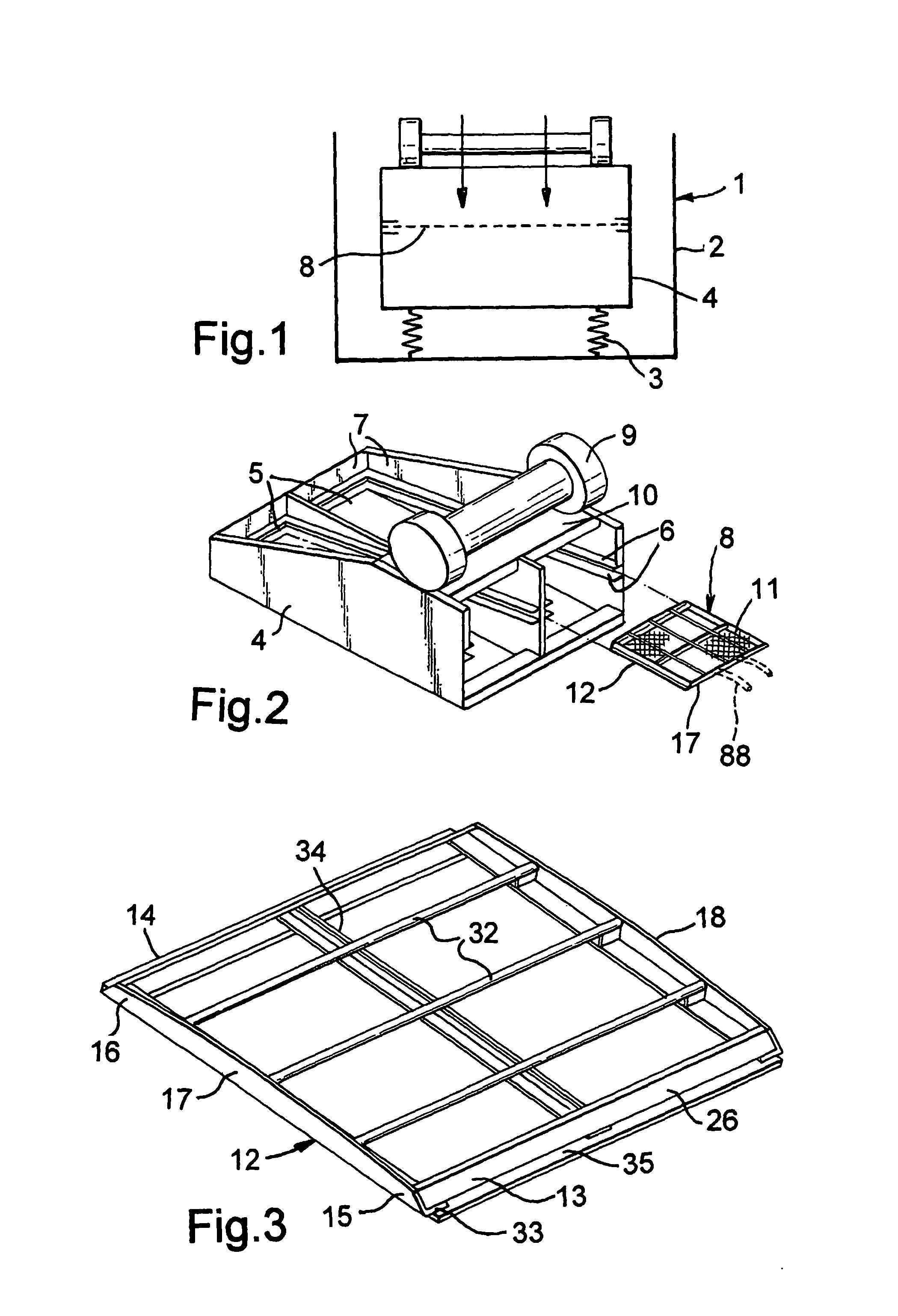
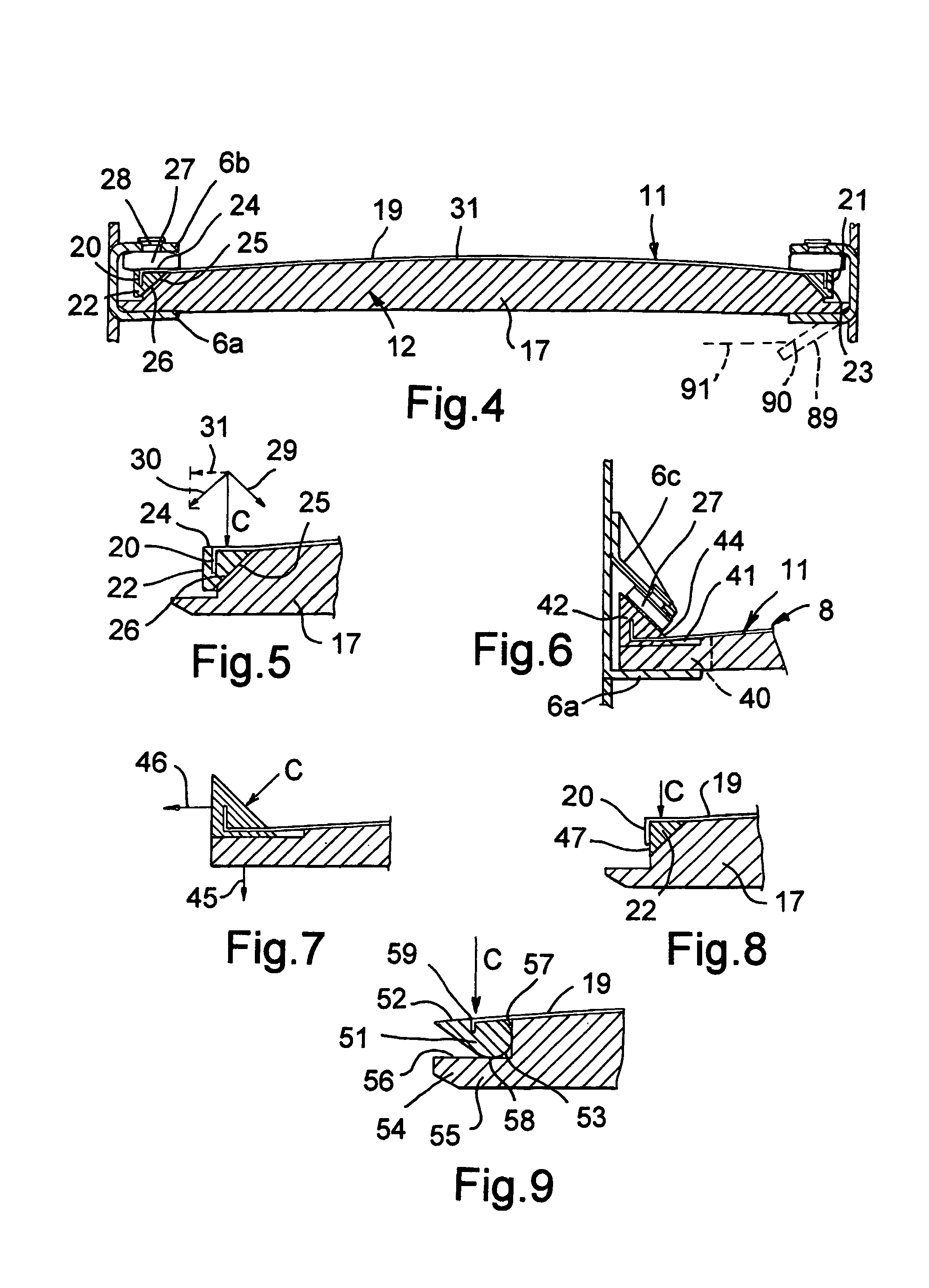
[0064]FIG. 1 shows schematically a vibratory screen apparatus 1 with an outer housing 2 in which is mounted on springs 3 a basket unit 4. Each basket 5 of the basket unit 4 (see also FIG. 2) is generally box shaped with a pair of circumferentially extending inwardly projecting flanges 6 at an intermediate height on the basket walls 7, for supporting a screen system of the invention 8 as typically found in existing pretension screen vibratory machinery. A vibrator unit 9 is secured to the top 10 of the basket unit 4. FIG. 4 shows a screen system 8 comprising a screen element 11 clamped to a support frame 12 (also shown in FIG. 3) between the basket flanges 6.

[0065]The support frame 12 comprises first and second elongate frame elements 13, 14 at opposite end portions 15, 16 and further elongate, third and fourth, frame elements 17, 18 interconnecting them.

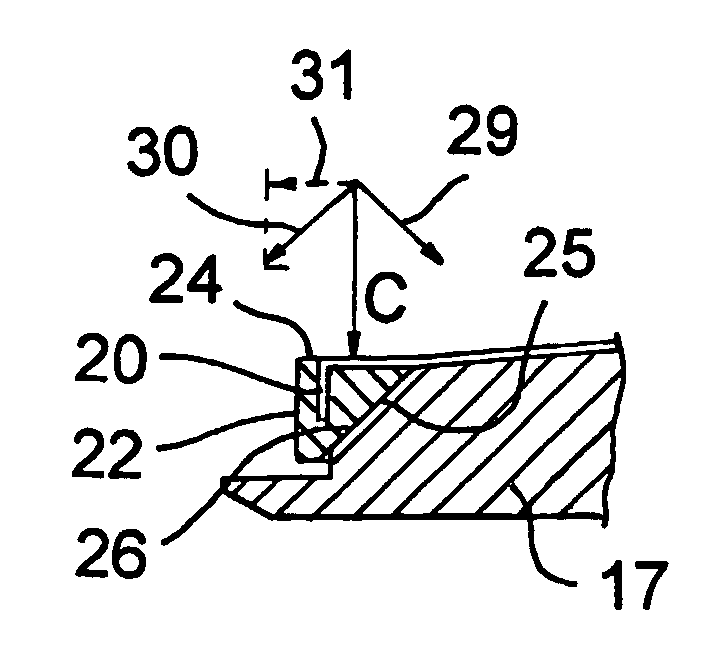
[0066]The screen element 11 comprises a mesh panel 19 having cranked opposite end portions 20, 21 anchored in first and second elon...


PUM

PropertyMeasurementUnit
Angleaaaaaaaaaa
Angleaaaaaaaaaa
Mesh sizeaaaaaaaaaa

Abstract

The present invention provides a screen system (8) suitable for use in a vibratory screen apparatus (1), and comprising: a screen element (11) and a support frame (12) therefor, as well novel screen elements (11) and mesh panels (19) therefor, and the use thereof. The screen element (11) consists essentially of a mesh panel (19) provided with first and second elongate support members (22, 23) extending along opposite end portions of the mesh panel (19). The support frame (12) has spaced apart first second elongate frame elements (13, 14) for engagement with the screen element support members (22, 23) and further elongate frame elements (17, 18) extending there between for supporting the mesh panel (19). The screen element support members (22, 23) and said first and second frame elements (13, 14) are formed and arranged for secure interengagement in use of the screen system, with at least one of said screen element support members and the respective one of said first and second frame elements being formed and arranged so that when clamped together, the mesh panel (19) is securely held under tension against said further frame elements (17, 18).

Description

FIELD OF THE INVENTION[0001]The present invention relates to screen systems for use in vibratory screen apparatus suitable for use in liquid solid separation and classification including inter alia, the sifting of drilling mud, cuttings and like material derived from oil-well drilling.BACKGROUND OF THE INVENTION[0002]Conventional vibratory apparatus for sifting mud and like material in the oil industry generally utilise screens of either hook strip or pretensioned design. Hook strip screens generally consist of single or multiple layers of mesh bonded together, which are tensioned after mounting in the basket of the vibratory screen apparatus. Two opposed ends of the screen are fitted with a turn back element to form a hook strip which is hooked around a tension rail, the latter being attached to the side wall of the basket, typically via a tension bolt, though other loading means to apply tensioning and securing forces may be employed. Tightening the tension bolt moves the tension ...

Claims


Application Information

Patent Timeline
IPC IPC(8): B07B1/49B01D33/03B07B1/48
CPCB01D33/0376B07B1/48B07B1/49
Inventor FISHER, GEORGE WILLOXBAILEY, MARSHALL GRAHAM
Owner NAT OILWELL VARCO UK
Why Eureka
Try Eureka