Inkjet recording apparatus and method for controlling same

a recording apparatus and inkjet technology, applied in the field ofinkjet recording techniques, can solve the problems of high defect rate, difficult to form piezoelectric elements and heating resistance elements over the entire width of the recording area without any defects, and difficult to form inkjet print elements corresponding to such a large number of nozzles without defects, etc., to achieve the effect of reducing the degree of “connection lines” in the boundary region between the bands and increasing the print quality of the image obtained by the head assemblies

Inactive Publication Date: 2007-05-15
CANON KK
View PDF4 Cites 9 Cited by
  • Summary
  • Abstract
  • Description
  • Claims
  • Application Information

AI Technical Summary

Benefits of technology

[0020]In view of the above-described problems, an object of the present invention is to provide a technique for preventing the “connection lines” from being formed at boundaries between the bands due to the temperature variation between the head chips when single-path recording is performed using a head assembly.
[0034]As described above, according to the present invention, recording is performed by a single-path method using a long head assembly obtained by disposing a plurality of head chips, each having multiple nozzles arranged therein, in the arrangement direction of the nozzles, and the discharge of the ink is controlled on the basis of the temperature detected for each head chip or heater board. Accordingly, the degree of “connection lines” in the boundary regions between the bands is reduced and the print quality of the image obtained by the head assembly is increased.

Problems solved by technology

However, when the above-described long head is manufactured, it is extremely difficult to form the nozzles and print elements, such as piezoelectric elements and heating resistance elements, over the entire width of the recording area without any defects.
It is difficult to form inkjet print elements corresponding to such a large number of nozzles without any defects in view of the manufacturing process thereof.
Even if it is possible to manufacture such a print head, the percentage of defects is high and extremely high costs are incurred.
The above-described problem of variation in heat generation is particularly crucial in the bubble jet recording method.
Therefore, heat is transmitted between the head chips via a base plate composed of, for example, alumina, carbon, aluminum metals, etc., to which the head chips are adhered, and the temperature variation between the head chips is too large to be ignored when the head assembly is used.

Method used


Image

  • Inkjet recording apparatus and method for controlling same
  • Inkjet recording apparatus and method for controlling same
  • Inkjet recording apparatus and method for controlling same

Examples


first embodiment

[0055]According to a first embodiment, a bubble jet head is used for discharging ink, and the volume of ink drops is changed by a discharge control unit on the basis of temperature data obtained by detecting the temperature of each head chip or heater board.

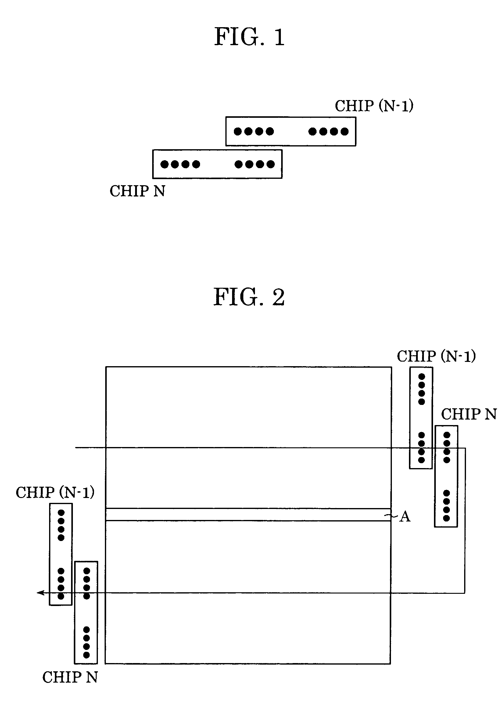
[0056]In addition, a head assembly is structured such that two short chips are shifted from each other in a direction orthogonal to the arrangement direction of the nozzles and the chips overlap each other by at least one nozzle in the arrangement direction of the nozzles, as shown in FIG. 1.

[0057]The manner in which an image is recorded on a recording medium using this head by the single path method is shown in FIG. 2. In FIG. 2, a region denoted by A shows a band boundary region which is printed twice during two successive scans of the recording head. In this example, the band boundary region A is printed twice by nozzles at the bottom of the chip N in the first scan and nozzles at the top of the chip (N−1) in the next scan.

[00...

second embodiment

[0089]In a second embodiment, a bubble jet head is used as an inkjet head, and the number of ink drops discharged is changed by a discharge control unit on the basis of data obtained by detecting the temperature of the head.

[0090]FIG. 11 shows an example of the state of dots recorded in a boundary region between two head chips. In the figure, the state of ink discharged by nozzles (the state of dots being recorded) in the band boundary region is shown.

[0091]The positional relationship between the two head chips shown in FIG. 11 is similar to that shown in FIG. 2. In order to facilitate understanding, the head chips are shown in FIG. 11 in the orientation different from that in FIG. 2.

[0092]FIG. 11 shows the state in which the temperature of each head chip is normal (the temperatures of the two head chips are both in a predetermined range and are substantially equal) and dots are evenly recorded by the nozzles of the chip N and the chip (N−1) in the band boundary region. More specifi...

third embodiment

[0103]In the first and the second embodiments, the discharge control of the nozzles in the overlapping region is performed by directly detecting the temperature of each chip.

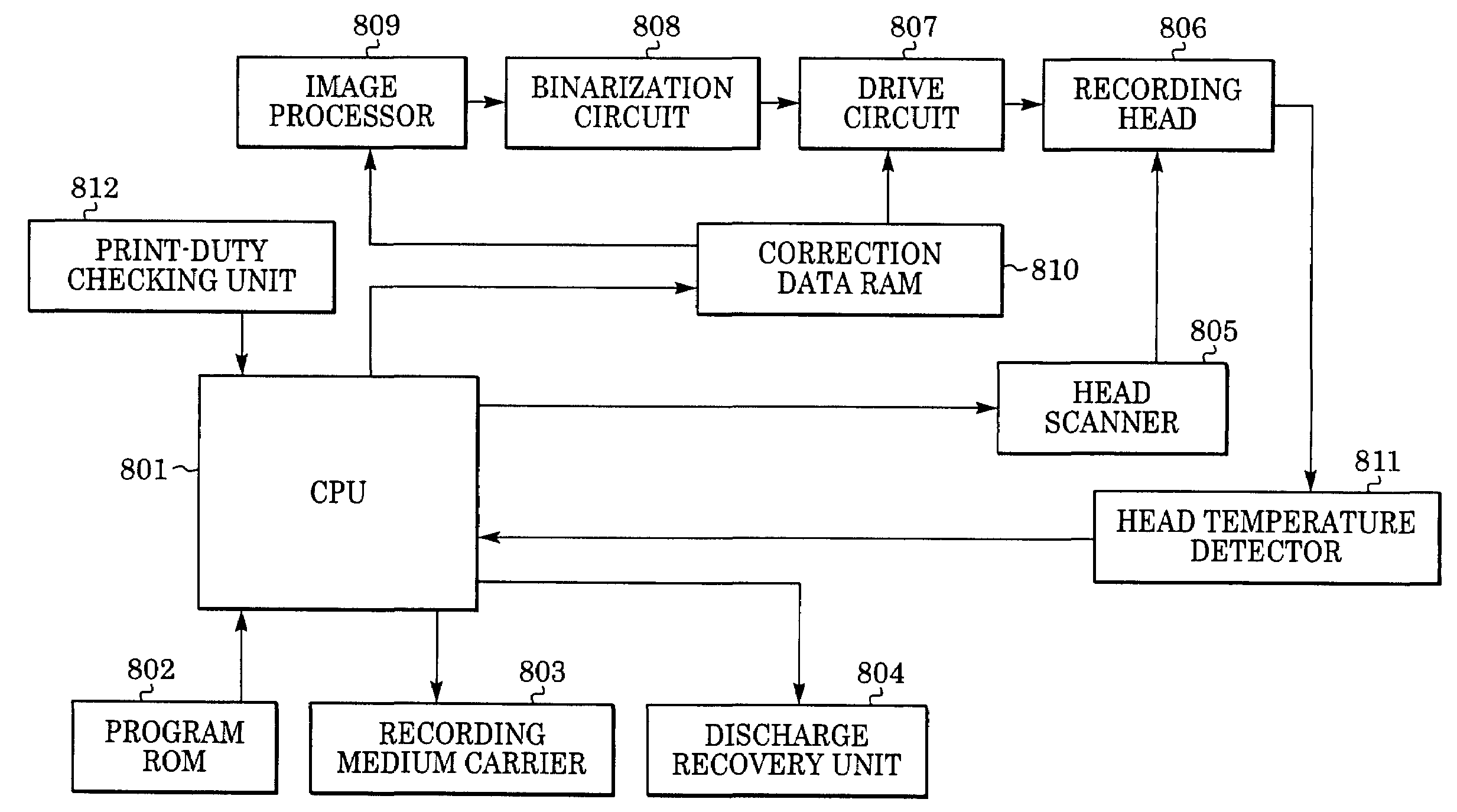
[0104]In a third embodiment, the discharge control is performed using the output from the print-duty-checking unit 812 shown in FIG. 8.

[0105]First, the image data to be recorded is expanded in the print-duty-checking unit 812. The print-duty-checking unit 812 has a large-capacity memory, and the number of ink drops discharged from each nozzle in the head assembly can be checked by expanding the image memory corresponding to a single page. The large-capacity memory may be, for example, a hard disc, a semiconductor memory such as DRAM, a flash memory, a card memory, etc. Here, the important information is the number of ink drops discharged in the regions outside the band boundary regions in each chip. The number of nozzles in the band boundary regions is normally smaller than the number of nozzles in the regions o...


PUM


Abstract

An inkjet recording apparatus includes a head assembly in which a plurality of head chips, each having multiple nozzles arranged therein for discharging ink, are disposed in the arrangement direction of the nozzles. The discharge of ink from the nozzles of each head chip in band-boundary regions in which bands recorded by the head chips overlap each other is adjusted in accordance with the detection result of the temperature of each head chip.

Description

BACKGROUND OF THE INVENTION[0001]1. Field of the Invention[0002]The present invention relates to inkjet recording techniques in which recording is performed by discharging ink toward a recording medium from a long recording head (hereafter called a head assembly) obtained by connecting a plurality of head chips, each having multiple nozzles. More specifically, the present invention relates to an inkjet recording technique in which an image is recorded on a recording medium with a single scan of a head assembly relative to the recording medium (single-path method). The head assembly is obtained by disposing a plurality of relatively short head chips, each having multiple nozzles arranged therein, in the arrangement direction of the nozzles with high accuracy.[0003]2. Description of the Related Art[0004]In printers, printing apparatuses used in copy machines or the like, and printing apparatuses used as output apparatuses in workstations or complex electronic systems including compute...

Claims


Application Information

Patent Timeline
Patent Type & Authority Patents(United States)
IPC IPC(8): B41J29/393B41J29/38B41J2/01B41J2/05B41J2/145
CPCB41J2/04528B41J2/04563B41J2/0458B41J2/04588B41J2/04591B41J2/04598B41J2/145B41J2202/20
Inventor WADA, SATOSHIYAMAGUCHI, HIROMITSUYOSHINO, HITOSHI
Owner CANON KK
Why Eureka
Try Eureka