Plasma process chamber and system

Active Publication Date: 2007-05-15
CHOI DAE KYU
View PDF27 Cites 23 Cited by
  • Summary
  • Abstract
  • Description
  • Claims
  • Application Information

AI Technical Summary

Benefits of technology

[0009]Accordingly, it is an object of the present invention to provide a plasma process chamber capable of obtaining high uniformity and density of the plasma.
[0010]It is another object of the present invention to provide a plasma process chamber in which plasma ion

Problems solved by technology

In a plasma related application, how to realize stable generation of plasma and to provide high ionization efficiency for the plasma have become continuous problems to be solved by technical experts of this art.
In addition, s

Method used


Image

  • Plasma process chamber and system
  • Plasma process chamber and system
  • Plasma process chamber and system

Examples


embodiment 1

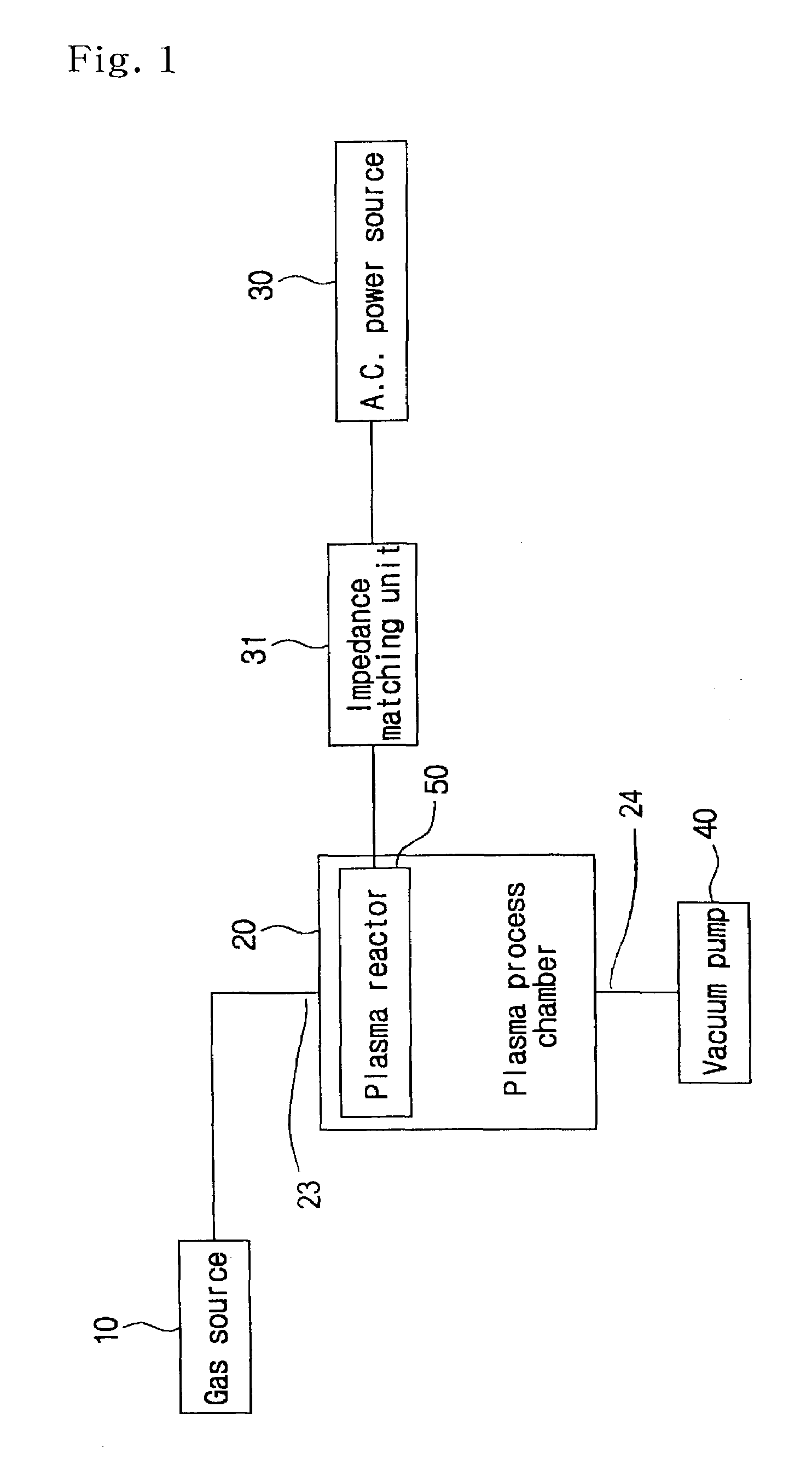
[0052]FIG. 1 is a schematic block diagram of a plasma process system according to a first preferred embodiment of the present invention.

[0053]Referring to the drawings, the plasma process system according to a first preferred embodiment of the present invention generally includes a gas source 10, a plasma process chamber 20, an A.C. (alternating current) power source 30, an impedance matching unit 31, a vacuum pump 40, and a plasma reactor 50.

[0054]The plasma reactor 50 may be placed in the plasma process chamber 20 integrally or separately, although the plasma reactor is placed in the plasma process chamber 20 separately in this embodiment. The vacuum pump 40 is provided to keep uniform vacuum in the plasma process chamber 20 and to discharge gas after the process has been carried out.

[0055]Process gas is supplied from the gas source 10 to the plasma process chamber 20, and an actuating power is supplied from the A.C. power source 30 to the plasma reactor 50 so that plasma reaction...

embodiment 2

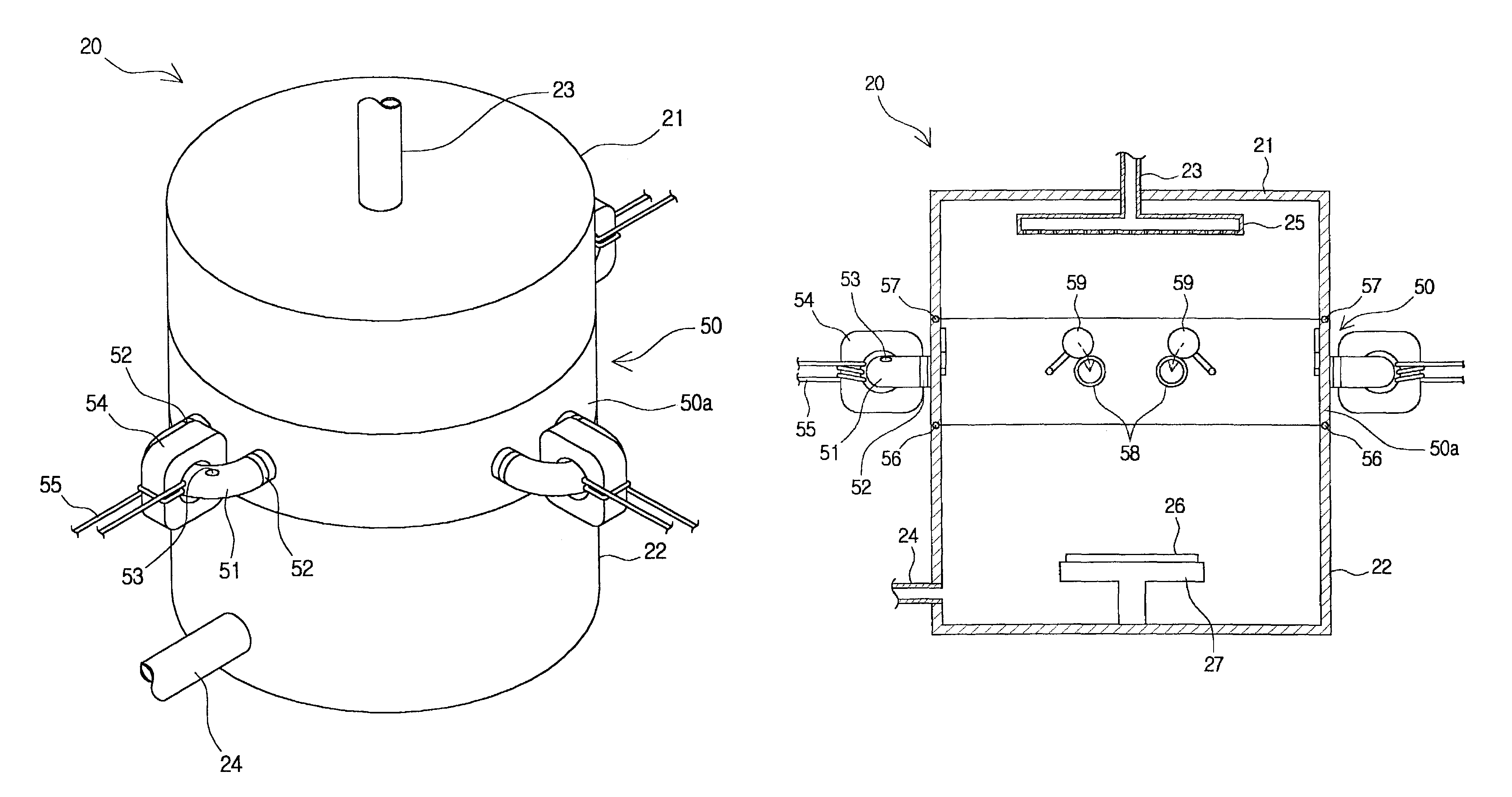
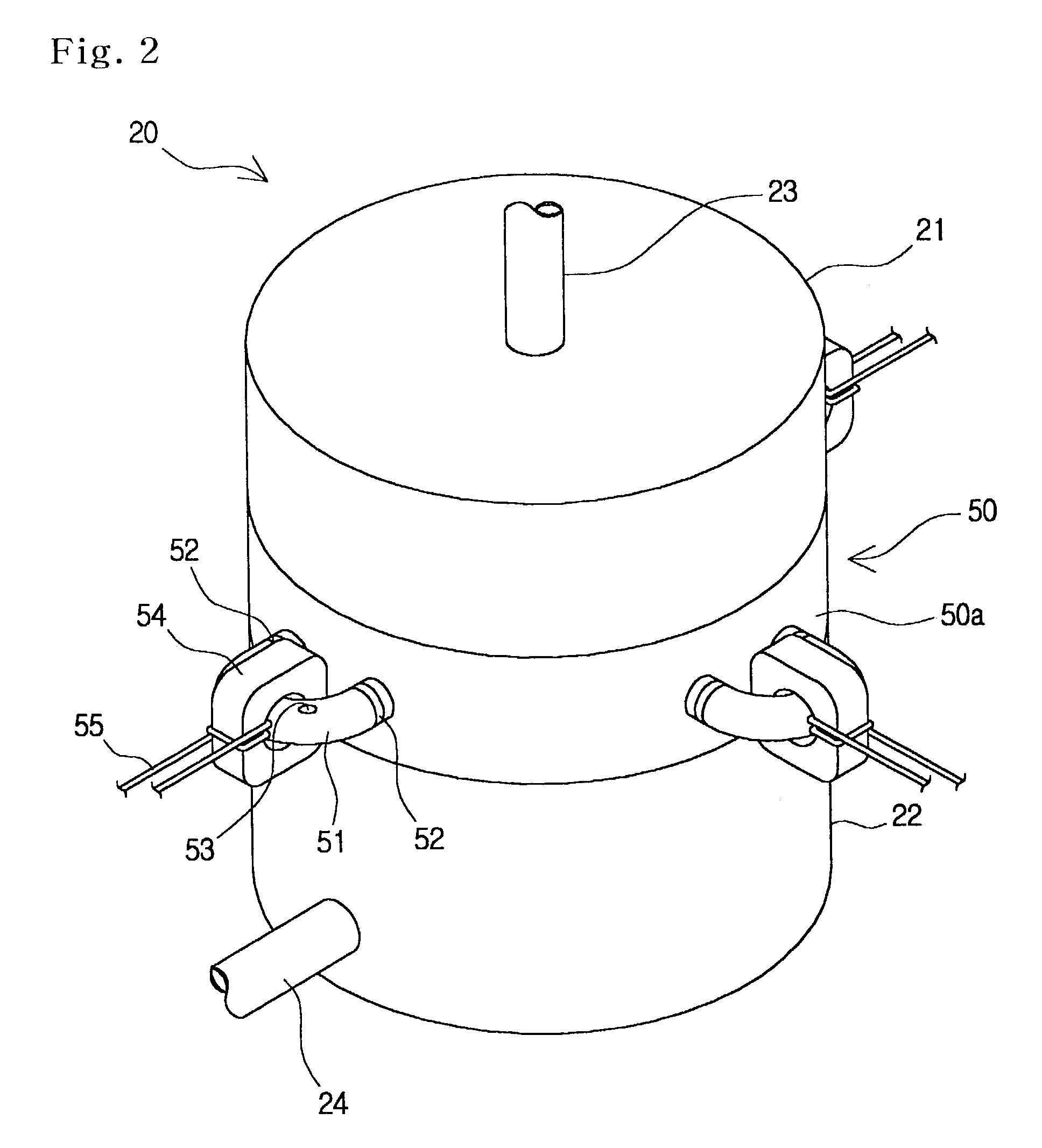
[0063]FIG. 5 is a schematic block diagram of a plasma process system according to a second preferred embodiment of the present invention, FIG. 6 is a perspective view of a plasma process chamber shown in FIG. 5, FIG. 7 is a plan view of a plasma reactor shown in FIG. 6, and FIG. 8 is a cross sectional view of the plasma process chamber shown in FIG. 6.

[0064]Referring to the drawings, the plasma process system according to a second preferred embodiment of the present invention generally includes a first gas source 10, a second gas source 12, a plasma process chamber 20, an A.C. power source 30, an impedance matching unit 31, a 14 vacuum pump 40, and a plasma reactor 50.

[0065]The first gas source 10 is provided to store process gas, which is used to carry out a wafer manufacturing process, while the second gas source 12 is provided to store cleaning gas, which is used to clean the plasma process chamber 20. In this embodiment, the process gas flows directly in the plasma process chamb...

embodiment 3

[0068]FIG. 9 is a schematic block diagram of a plasma process system according to a third preferred embodiment of the present invention.

[0069]Referring to the drawings, the plasma process system according to a third preferred embodiment of the present invention generally includes a first gas source 10, a second gas source 12, a plasma process chamber 20, a first A.C. power source 30, a second A.C. power source 32, a first impedance matching unit 31, a second impedance matching unit 33, a vacuum pump 40, and a plasma reactor 50.

[0070]The first A.C. power source 30 is connected to the plasma reactor 50 via the first impedance matching unit 31 for supplying ionization energy for plasma reaction, while the second A.C. power source 32 is provided to supply diffusion energy to the plasma gas in the plasma process chamber 20 via the second impedance matching unit 33. Here, the diffusion energy means the energy for diffusing the plasma gas evenly in the plasma process chamber 20.

[0071]FIG. ...


PUM


Abstract

The present invention relates to a plasma process chamber, which includes: an upper housing having a gas inlet connected to a gas source, and a gas shower head placed in the upper housing; and a lower housing having a gas outlet connected to a vacuum pump, and a substrate provided on the inner bottom of the lower housing. On the substrate is placed a wafer. A plasma reactor is provided between the upper housing and the lower housing of the plasma process chamber. The plasma reactor is provided on the outer circumference of its main body with at least one reactor tube of horseshoe shape. A closed magnetic core is attached to the reactor tube, and a coil is wound on said magnetic core. The coil is connected electrically to an A.C. power. The plasma reactor is placed in the middle area of the plasma process chamber and a plurality of the reactor tubes are provided on the outer circumference of the plasma reactor so that plasma reaction is generated and distributed evenly in the plasma process chamber. Consequently, high density of the plasma can be obtained. Furthermore, the generated plasma ion particles are diffused evenly in the plasma process chamber by the diffusion induction electrodes so that cleaning efficiency can be highly increased in the plasma process chamber.

Description

CLAIM OF PRIORITY[0001]This application makes reference to, incorporates the same herein, and claims all benefits accruing under 35 U.S.C. §119 from an application for “PLASMA PROCESS CHAMBER AND SYSTEM” earlier filed in the Korean Patent Office on Nov. 14, 2002, and there duly assigned Ser. No. 2002-70690 by that office.BACKGROUND OF THE INVENTION[0002]1. Field of the Invention[0003]The present invention relates generally to a plasma process chamber and system, and more particularly to a plasma process chamber and system of the structure that is capable of improving uniformity of plasma and generation density of plasma in the plasma process chamber when carrying out a process using plasma.[0004]2. Description of Related Art[0005]A plasma source is used widely in several processes for manufacturing semiconductor devices, for example such as etching, stripping, cleaning, etc. A plasma process chamber is used to manufacture the semiconductor devices while the processes, such as etchin...

Claims


Application Information

Patent Timeline
IPC IPC(8): C23F1/00C23C16/00H01L21/306H01L21/02H01J37/32
CPCH01J37/321H01L21/02
Inventor CHOI, DAE-KYU
Owner CHOI DAE KYU
Why Eureka
Try Eureka