Discharge lamp lighting circuit

a technology of discharge lamp and circuit, which is applied in the direction of light sources, process and machine control, instruments, etc., can solve the problems of increasing circuit scale and system cost, compromising compact design, and affecting the stability of lighting or blackout, so as to reduce the probability of unstable lighting or blackout, reduce the cost of circuit devices, and reduce the effect of tim

Inactive Publication Date: 2007-05-15
KOITO MFG CO LTD
View PDF2 Cites 3 Cited by
  • Summary
  • Abstract
  • Description
  • Claims
  • Application Information

AI Technical Summary

Benefits of technology

[0011]One or more embodiments of the invention keep a discharge lamp lit after it is started and reliably place the discharge lamp into a stable lighting state.
[0016]According to embodiments of the invention, the frequency is not changed from f1 to f2 immediately after the discharge lamp is initiated to be turned on by way of the start signal. Rather, shift control from f1 to f2 is continuously performed to gradually change the driving frequency. That is, control is performed so that a residence time in a frequency range lower than the resonance frequency (capacitive range or advanced-phase range) when the discharge lamp is turned on is secured and a shift is performed to a frequency range higher than Fon when the electrode of the discharge lamp is warmed up.
[0017]According to embodiments of the invention, it is possible to reliably keep lighting a discharge lamp after it is started, thereby substantially reducing the probability of unstable lighting or blackout. This approach does not involve a complicated circuit configuration or a complicated control method, which is advantageous in terms of a compact design and lower cost of a circuit device.
[0018]It is desirable that a frequency “fw” is set between f1 and f2 and control is performed to change the variation speed of a driving frequency from f1 to fw after the discharge lamp is lit from the variation speed of the driving frequency from fw to f2 after fw is reached in order to reduce the time from a time point the discharge lamp is started and lit to a stable lighting state. For example, assuming that the relationship “f1<fw<Fon” is held between F1, fw and Fon, in the case where the variation speed of the driving frequency changing from f1 to fw is represented as “Δf1w / Δt”, the variation speed of the driving frequency changing from fw to f2 is represented as “Δfw2 / Δt”, and the magnitude of the variation speeds are represented using an absolute value sign “||”, the relationship “|Δf1w / Δt|>|Δfw2 / Δt|” is held. By way of power control in the range less than Fon (the range where the circuit output impedance when the discharge lamp is on is capacitive), it is possible to shift the driving frequency to a frequency range higher than the resonance frequency Fon (inductive range or delayed-phase range) with the electrode of the discharge lamp warmed up. Thus, for example, it is possible to enhance the reliability of lighting at the cold start of a discharge lamp.
[0019]Setting the time period required for a shift from f1 to f2 to 10 milliseconds or more and one second or less is effective for prevention of flickering. The magnitude of the variation speed of the driving frequency is controlled to become smaller as the driving frequency approaches f2, which secures a sufficient residence time near Fon. This alleviates the temporal change in the lamp current and amount of light. For example, this contributes to the safety in nighttime operation in an application to a lighting fixture for a vehicle.
[0020]In order to simplify the control design, it is preferable to use a time constant circuit for changing the driving frequency of a switching element from f1 to f2. For example, it is possible to readily specify the variation speed of the driving frequency in accordance with switching between time constants or setting a time constant, without a complicated circuit design.

Problems solved by technology

Further, the larger the number of switching elements used in a DC-to-AC converter circuit becomes, the more problems arise with the circuit scale and the system cost.
In a configuration where voltage conversion is performed at two stages (DC voltage conversion and DC-TO-AC voltage conversion), the circuit scale could be increased, which compromises a compact design.
In particular, in a case where a discharge lamp is to be lit when it is cold (so-called “cold start”), an excessive input power exceeding a rated power is supplied to the discharge lamp.

Method used


Image

  • Discharge lamp lighting circuit
  • Discharge lamp lighting circuit
  • Discharge lamp lighting circuit

Examples


Embodiment Construction

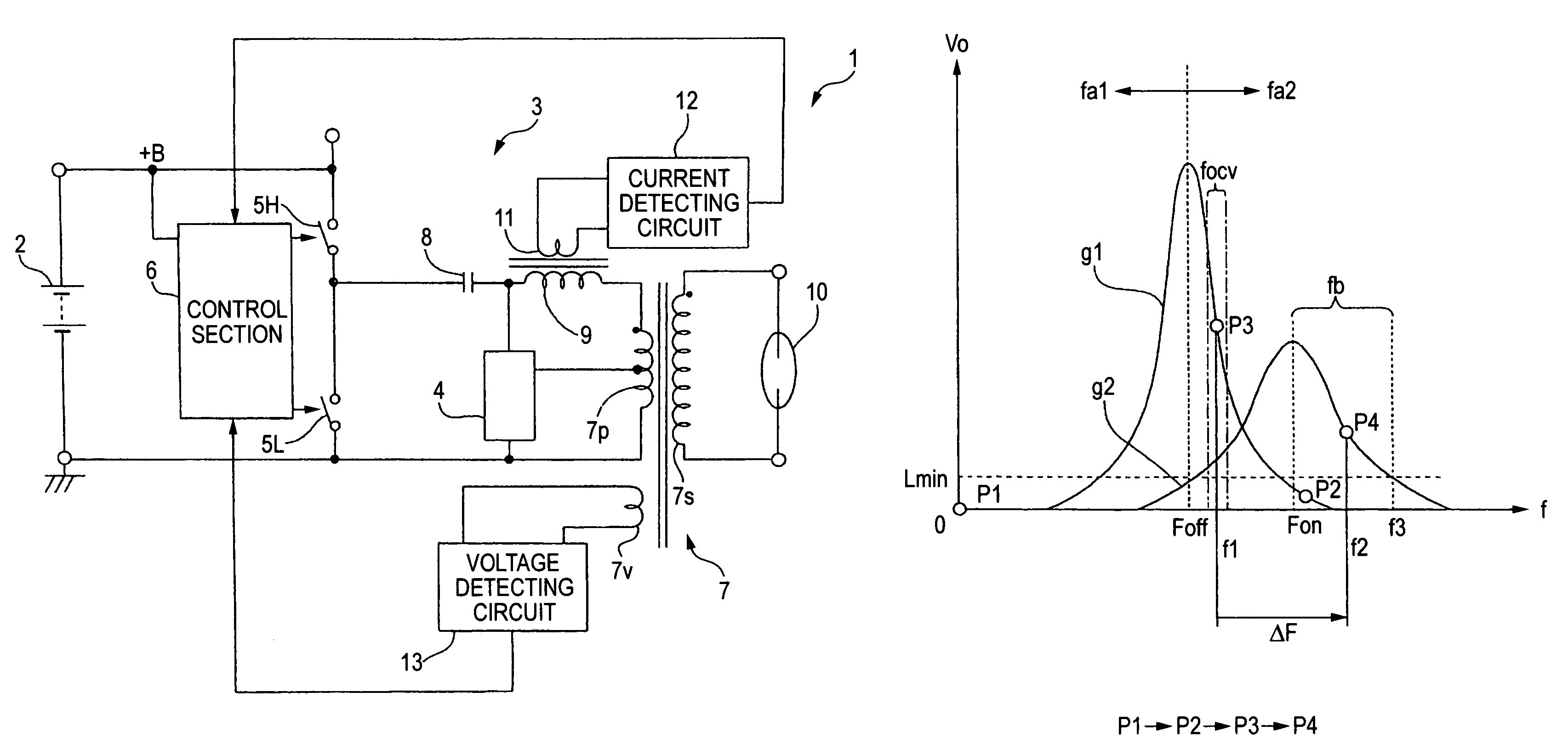
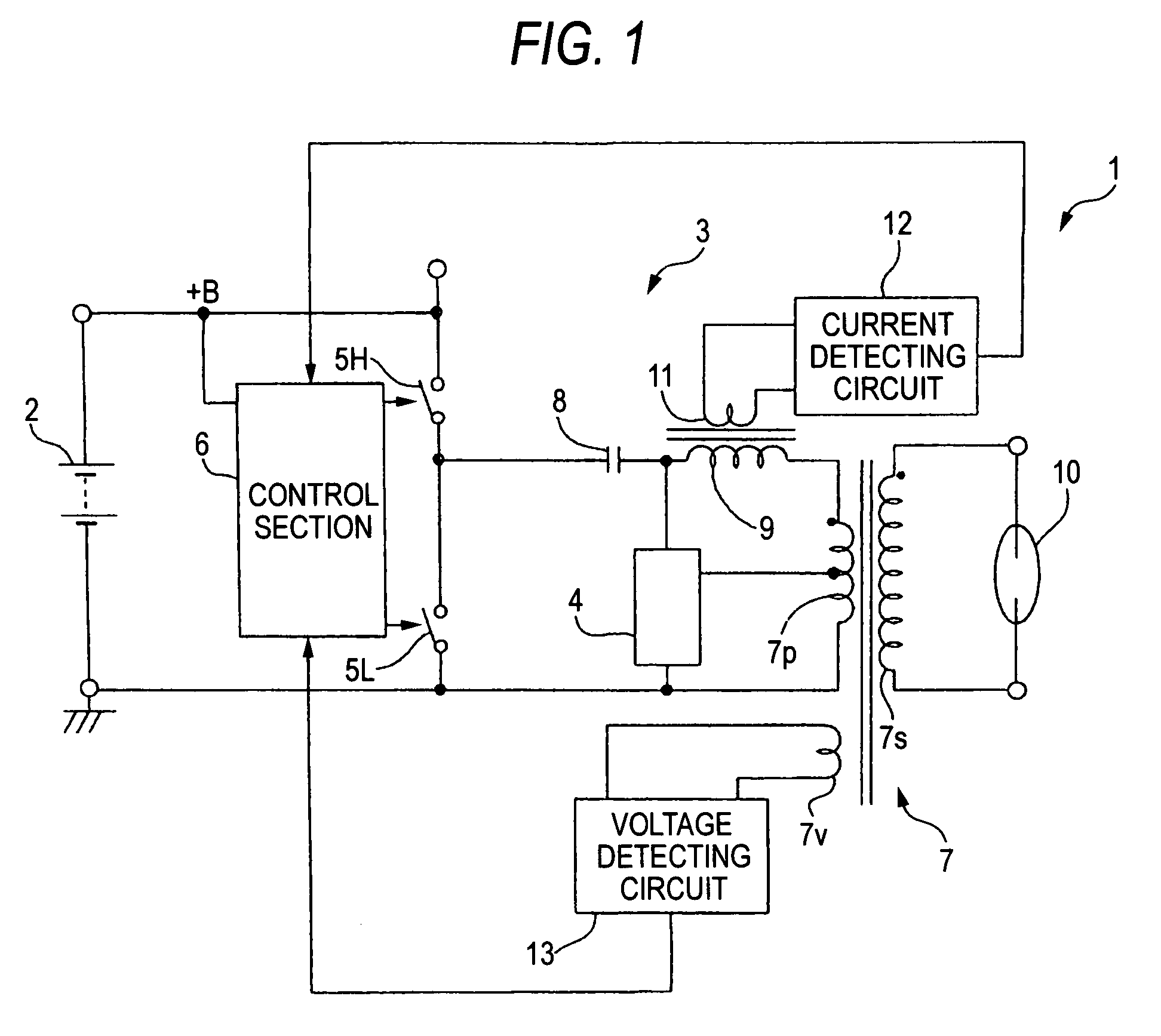
[0034]FIG. 1 shows a basic configuration example according to an embodiment of the invention. A discharge lamp lighting circuit 1 comprises a DC-to-AC converter circuit 3 and a starting circuit 4 to which power is supplied from a DC power supply circuit 2.

[0035]The DC-to-AC converter circuit 3 is provided to receive an input DC voltage (see “+B” in FIG. 3) from the DC power supply circuit 2 and convert the DC voltage to an AC voltage and boosting the resulting voltage. In this example, two switching elements 5H, 5L and a control section 6 for making drive control of the switching elements are provided. One end of the higher-stage switching element 5H is connected to the power supply terminal while the other end of the switching element is grounded via a lower-stage switching element 5L so that the elements 5H, 5L are alternatively turned on / off. While the elements 5H, 5L are shown by a switch signs for clarity in FIG. 1, a semiconductor switch such as a field-effect transistor (FET)...


PUM


Abstract

A control section is used to control a DC-to-AC converter circuit to perform lighting control of a discharge lamp. A transformer, switching elements, and a capacitor for resonance are included. The switching elements are driven and serial resonance of the capacitor and the inductance component of the transformer or an inductance element is produced. Before the discharge lamp is turned on, control is performed to cause the driving frequency of the switching elements to gradually approach Foff and to supply a start signal to the discharge lamp. Once the discharge lamp is turned on, control is performed to continuously change the driving frequency from f1 assumed before the discharge lamp is turned on to f2. A residence time in a frequency range lower than Fon is secured then the frequency is shifted to a frequency range fb higher than Fon, or an inductive range fb.

Description

CROSS-REFERENCE TO RELATED APPLICATIONS[0001]This application is based upon and claims the benefit of priority from the prior Japanese Patent Applications No. 2005-067203, filed on Mar. 10, 2005, the entire contents of which are incorporated herein by reference.BACKGROUND OF THE INVENTION[0002]1. Field of the Invention[0003]The present invention relates to a technique for reliably shifting to a stable lighting state after a discharge lamp is turned on in a discharge lamp lighting circuit suited for compact design and supporting high-frequencies.[0004]2. Description of the Related Art[0005]There is known a lighting circuit for a discharge lamp such as a metal halide lamp having a DC power supply circuit designed as a DC-to-DC converter, a DC-to-AC converter circuit, and a starter circuit. For example, an input DC voltage from a battery is converted to a desired voltage in the DC power supply circuit and then converted to an AC output in the DC-to-AC converter circuit downstream of th...

Claims


Application Information

Patent Timeline
Patent Type & Authority Patents(United States)
IPC IPC(8): G05B1/00
CPCH05B41/2883H05B41/382
Inventor MURAMATSU, TAKAO
Owner KOITO MFG CO LTD
Why Eureka
Try Eureka