Dynamic feedback linearization

Active Publication Date: 2007-05-15
QORVO US INC
View PDF9 Cites 31 Cited by
  • Summary
  • Abstract
  • Description
  • Claims
  • Application Information

AI Technical Summary

Benefits of technology

[0010]The objects, features and advantages of the present invention include providing an active feedback dynamic bias circuit that may (i) be compact and cost effective, (ii) be implemented with Darlington gain blocks and/or matched power amplifiers, (iii) use a dynamic feedback bias network including a transistor in parallel with a threshold sensing network, such as a resistive divider, (iv) implement a bypass capacitor to remove the dynamic feedback network from the RF feedback path, (v) implement a base bypass capacitor to allow average th

Problems solved by technology

Such implementations have extra control ports, and can

Method used


Image

  • Dynamic feedback linearization
  • Dynamic feedback linearization
  • Dynamic feedback linearization

Examples


Embodiment Construction

[0035]The present invention may implement a dynamic feedback linearization circuit. The present invention may offer several degrees of freedom to shape the manner in which a base current and / or collector current ramps up with input power. Such an implementation may allow a user to distinctly control the dynamic amplitude, phase, bias current response, and linear dynamic range.

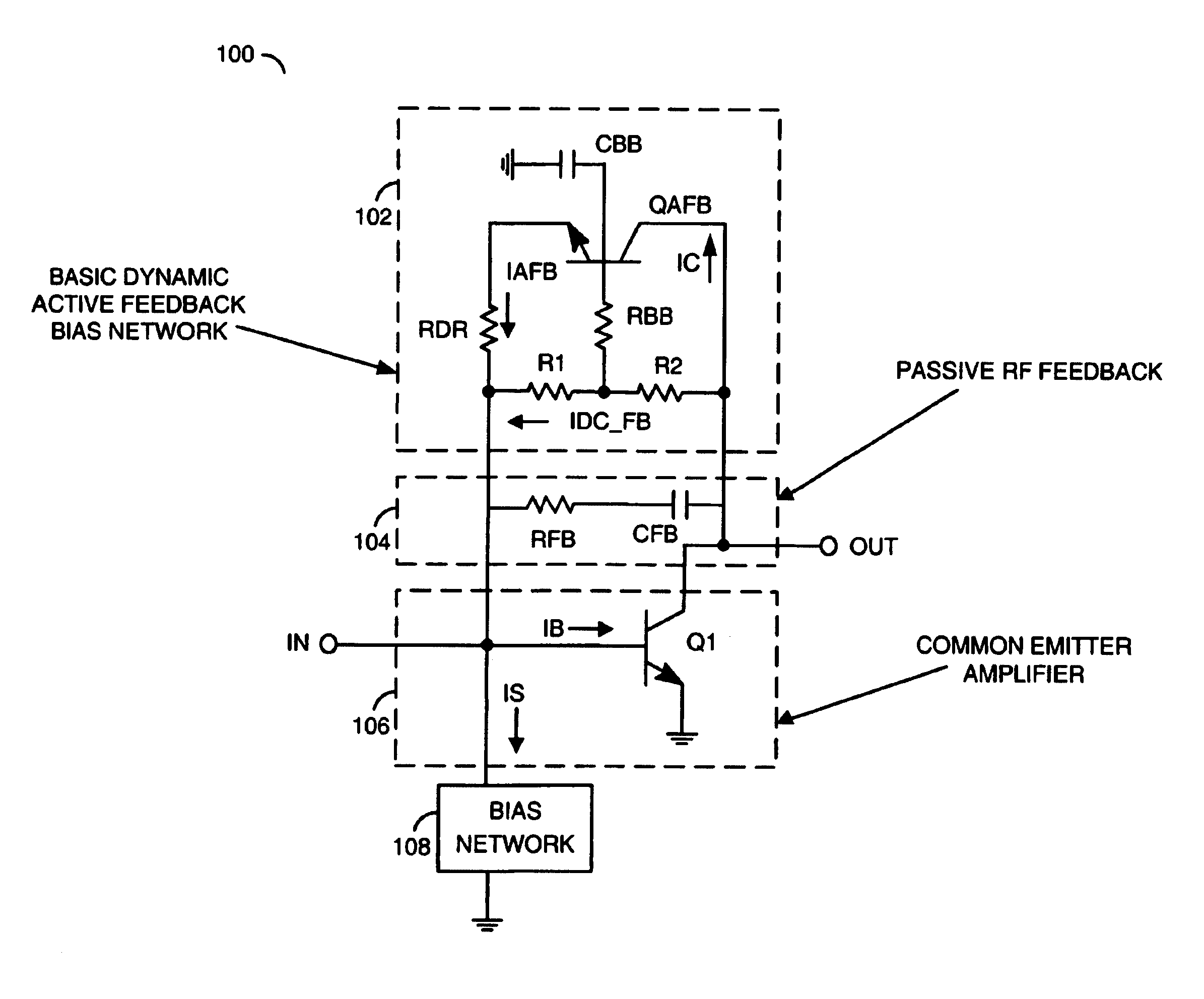
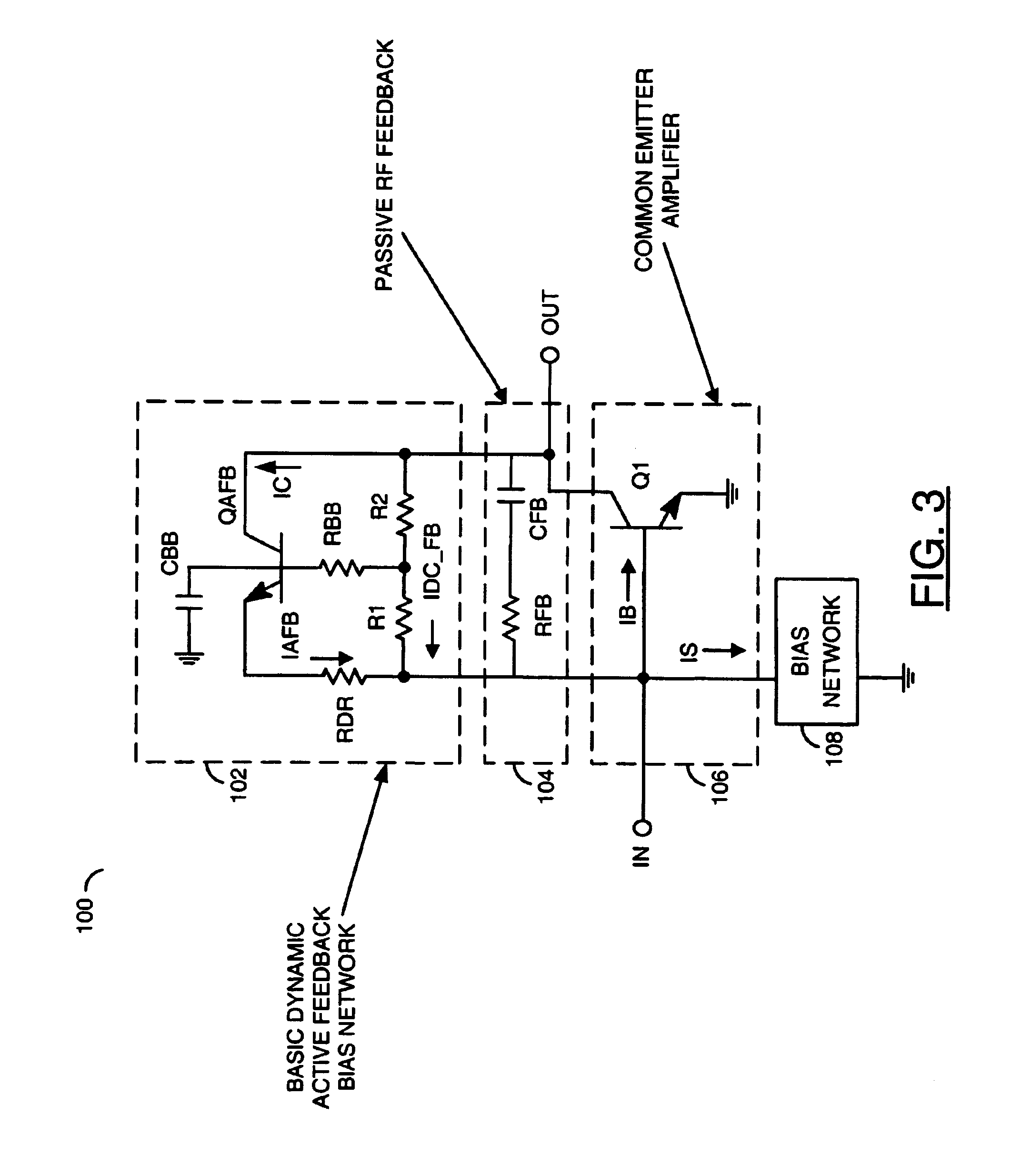
[0036]Referring to FIG. 3, a block diagram of a circuit 100 is shown in accordance with a preferred embodiment of the present invention. The circuit 100 generally comprises a block (or circuit) 102, a block (or circuit) 104, a block (or circuit) 106 and a block (or circuit) 108. The circuit 102 may be implemented as a dynamic active feedback bias network. The circuit 104 may be implemented as a passive RF feedback circuit. The circuit 106 may be implemented as an amplifier circuit. The circuit 108 may be implemented as a bias circuit. The circuit 102 generally comprises a transistor QAFB, a capacitor CBB, a res...


PUM


Abstract

An apparatus comprising an amplifier comprising at least one amplifier transistor, a threshold detection network and a bypass capacitor. The amplifier may be configured to generate an output signal at a collector in response to an input signal received at a base. The threshold detection network may be coupled between the collector and the base of the amplifier transistor. The threshold detection network may include a bias transistor having a collector coupled to the collector of the amplifier transistor and an emitter coupled to the base of the amplifier transistor. The threshold detection circuit may be configured to (i) sense a feedback current and (ii) provide a DC signal to the base of the amplifier transistor for dynamically sourcing bias current to the amplifier. The bypass capacitor may be coupled to the base of the bias transistor.

Description

FIELD OF THE INVENTION[0001]The present invention relates to amplifiers generally and, more particularly, a method and / or architecture for implementing dynamic feedback linearization that may be used in a low noise gain block or power amplifier.BACKGROUND OF THE INVENTION[0002]For new wireless systems such as WLAN and Wi-MAX, power amplifiers with high linear efficiencies are needed. Some sort of class AB or dynamic biasing is typically used to obtain high linear efficiencies. Other applications such as high dynamic range receivers can also benefit from dynamic biasing. Such receivers improve the input compression of a low noise amplifier (LNA).[0003]Conventional approaches implement class AB configurations as a popular solution. Many implementations are used, most of which include external manual tuning of resistors. Such implementations have extra control ports, and can be very sensitive to process or temperature variations.[0004]Referring to FIG. 1, an example of a circuit 10 ill...

Claims


Application Information

Patent Timeline
IPC IPC(8): H03F1/30
CPCH03F1/0288H03F1/30H03F1/34H03F3/189
Inventor KOBAYASHI, KEVIN W.
Owner QORVO US INC
Why Eureka
Try Eureka