Generating unit and method for producing a current with a predetermined network frequency

a technology of generating unit and network frequency, which is applied in the direction of electric generator control, dynamo-electric converter control, control system, etc., can solve the problems of reducing the flexibility of the design of torque-producing components, unable to achieve satisfactory efficiencies, and neither approach is suitable for high output power, etc., to achieve high stator voltage, compact and cost-effective, and better dynamic behavior of the drive

Inactive Publication Date: 2011-01-11
SIEMENS AG
View PDF19 Cites 1 Cited by
  • Summary
  • Abstract
  • Description
  • Claims
  • Application Information

AI Technical Summary

Benefits of technology

[0028]The proposed concept is particularly suitable for use in the power station sector and also in areas where the proposed generating unit is used as a peak-load device or as a mobile power generating unit. Especially in the latter case, the clearly better dynamic behavior of the drive and the generator effected due to the concept according to the invention is namely of advantage, wherein however a pre-defined stator rotary field frequency can be provided for a network mode, which does not necessarily have to fulfill the stability requirements of large power networks. A further advantage of the present concept consists in the fact that the proposed generating unit enables a particularly wide-band production of rotor voltages on the one hand and stator voltages on the other. The generating unit can therefore advantageously be used with moderate rotor voltages in the sub-kilovolt range to provide particularly high stator voltages in the range of 10 kV or more, for example with a power output in the kilowatt to 100 kilowatt range. In each case, the frequency converter (inverter) could be designed in a particularly compact and cost-effective manner, as it only has to convert the rotor power. That is to say that, compared with a state-of-the-art design in which the whole outgoing power of the generator is usually converted, there is the advantage that the electrotechnical control components have to convert a lower power. Quite generally, the speed of the shaft generating the power, i.e. the speed of the drive, can be selected to be independent of the network frequency and yet any constant or even variable stator rotary field frequency can be achieved. This allows the construction of the drive components to be more efficient and more compact. For example, with a super-synchronous operation of the generator, gearbox input drive speeds of more than 3,000 rpm or 3,600 rpm respectively can thus be realized—this corresponds to the synchronous speeds of two-pole rotary field machines at 50 Hz and 60 Hz network frequency respectively. With a four-pole generator, the abovementioned rpm figures are half as big, and with a six-pole generator the abovementioned rpm figures must be divided by three.
[0029]Unlike a purely synchronous machine, with the concept of an adjustable synchronous machine according to the invention presented here, the rotary field electromotive force can therefore be influenced directly with regard to its rotary field frequency effective for the stator. With appropriate regulation, this results not only in a considerably better dynamic behavior, but also allows a unit to be built for different or variable or possibly strongly transient network frequencies within the framework of network fluctuations. The generating unit according to the concept according to the invention is therefore primarily matched to the network frequency by means of an electrotechnical regulation of the rotational speed of the rotary field electromotive force. In doing so, the regulating device can be designed for a setpoint representing a stator rotary field frequency, wherein the stator rotary field frequency usually corresponds to a network frequency. In this case, a network frequency can particularly be a standard frequency of 50 Hz or 60 Hz. In principle, any other or any varying frequency in the form of the stator rotary field frequency can be achieved.
[0036]The drive is preferably designed in the form of a turbine and / or a flywheel. The flywheel can sit on a drive shaft, for example, and thus increase the mass of the shaft. In this way, energy can be buffered and taken off in the event of a peak network load, for example. If necessary, the drive can be formed exclusively by the flywheel. By decoupling the drive speed from the network frequency, the kinetic energy stored in the shaft train can be fully utilized in a controlled manner, namely in the event of short-term load peaks.
[0038]As part of a particularly preferred improvement of the generating unit, the width of an air gap between rotor and stator lies between 1 cm and 8 cm. While namely, in the case of asynchronous machines, the air gap generally lies in the range of a few millimeters and in the case of synchronous machines can be greater than 10 cm, the air gap set within the framework of the improvement takes into account the special design of the generator of the present concept in variable frequency operation. On the one hand, reactions by the stator on the field are prevented, and on the other hand a reactive power is kept as low as possible as a result of the presently optimized air gap.

Problems solved by technology

This significantly restricts flexibility in the design of the torque-producing components—therefore of the drive, e.g. in the form of a gas, steam or water turbine or a piston engine or other drive unit.
However, neither approach is suitable for high output powers.
This procedure is capital-intensive and prone to losses, however, so that only unsatisfactory efficiencies can be achieved.
In summary, therefore, with high generator powers, the drive must necessarily rotate at network frequency or a fraction thereof, which constitutes an undesirable constraint when producing current by means of a generating unit.

Method used


Image

  • Generating unit and method for producing a current with a predetermined network frequency
  • Generating unit and method for producing a current with a predetermined network frequency
  • Generating unit and method for producing a current with a predetermined network frequency

Examples


Embodiment Construction

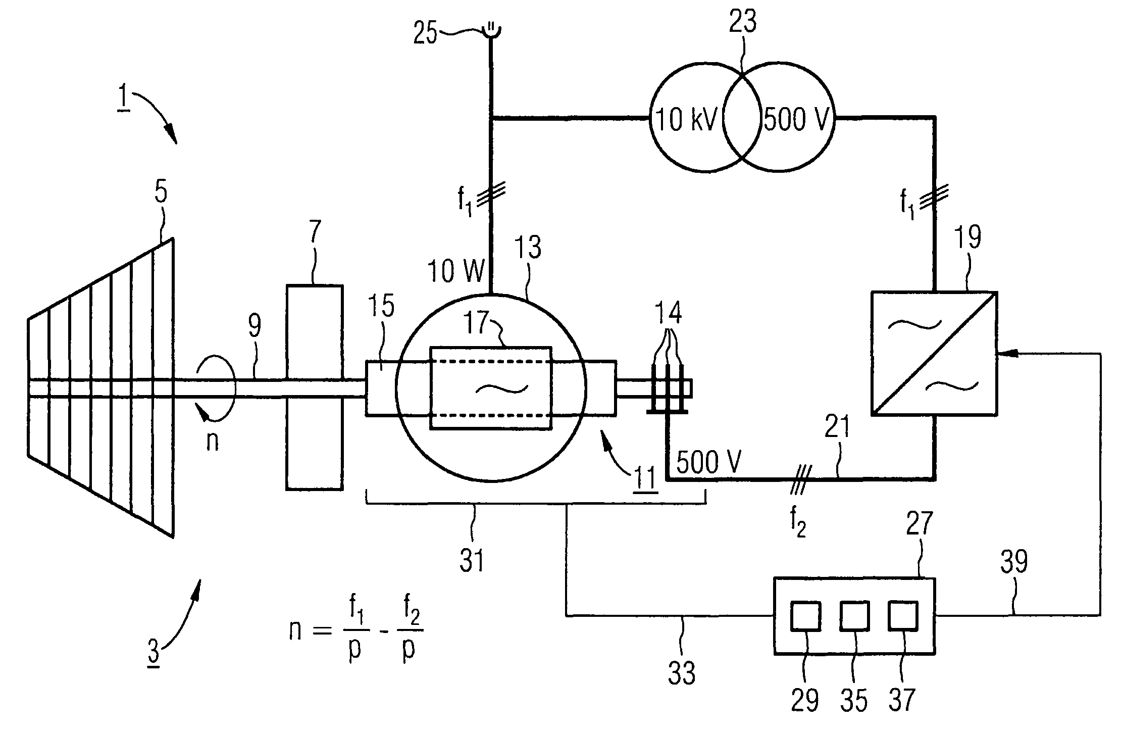
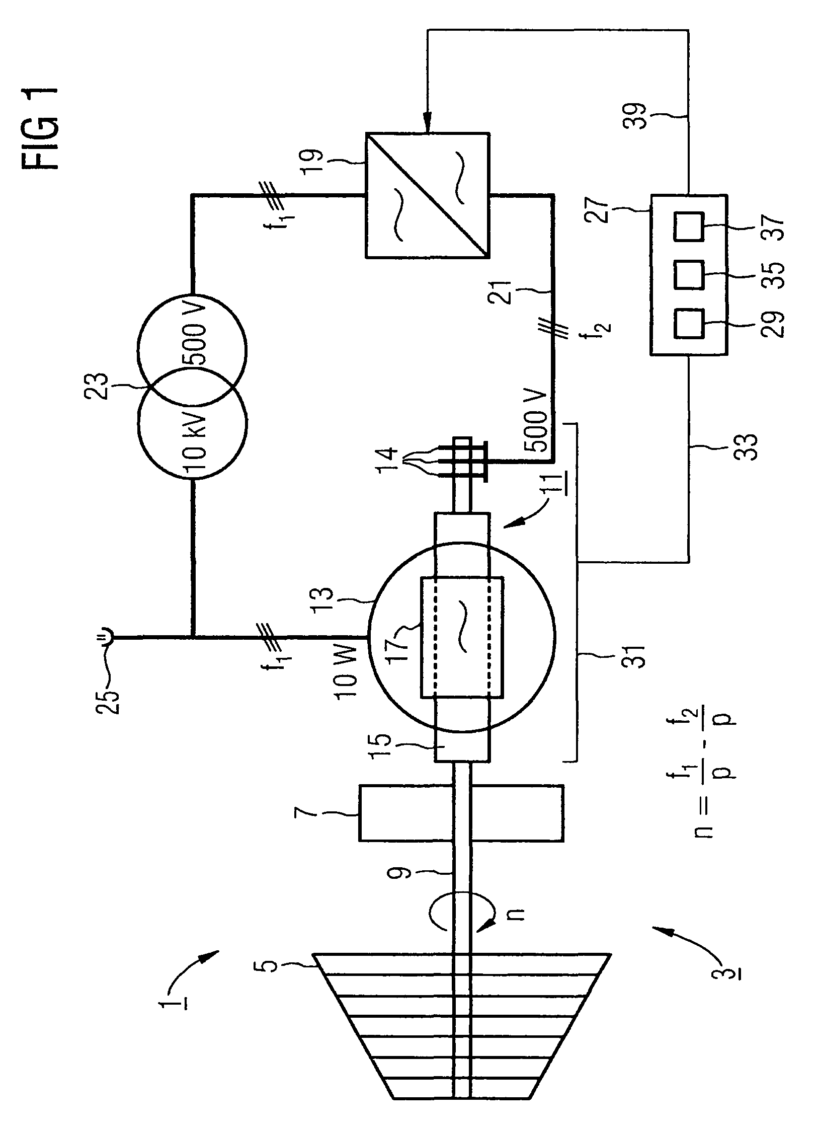
[0043]FIG. 1 shows a generating unit 1 with a drive 3, which here is constructed in the form of a turbine 5 and an additional flywheel 7. The drive 3 drives a generator 11 via a shaft train 9 with variable rotational frequency n. Here, the rotational frequency n is the frequency of rotation of the shaft train 9. The generator 11 is formed by a stator 13 and a rotor 15, the rotor 15 being coupled directly, i.e. without gearing, to the shaft train 9, and likewise rotating at variable rotational frequency n. That is to say, according to the preferred embodiment, the drive 3 is designed with variable rotational frequency n for driving the rotor 15.

[0044]In a conventional generator designed as a synchronous machine, this would lead in the case of a two-pole machine (number of pairs of poles p=1) to the rotational frequency n being equal to the stator rotary field frequency f1, as with conventional synchronous machines a stationary rotary field magnetomotive force is produced in relation ...


PUM


Abstract

A drive is embodied to drive a rotor at a variable rotational frequency; the rotor has a winding that is embodied to produce a rotary field magnetomotive force of a generator, with a rotor rotary field frequency which is variable in relation to the rotor; the frequency converter is electrically connected to the rotor winding; a regulating device comprises a recording element for measuring values of the generator, a calculating unit for a generator simulation, and a transmitter for transmitting a control signal to the frequency converter; and, on the basis of the control signal, an electrical excitation of the rotor winding can be triggered by the frequency converter in such a way that a pre-determined stator rotary field frequency is present in the event of a variable rotational frequency of the rotor and a variable rotor rotary field frequency.

Description

CROSS REFERENCE TO RELATED APPLICATIONS[0001]This application is the US National Stage of International Application No. PCT / EP2005 / 055882, filed Nov. 10, 2005 and claims the benefit thereof. The International Application claims the benefits of European application No. 05000257.5 filed Jan. 7, 2005, both of the applications are incorporated by reference herein in their entirety.FIELD OF INVENTION[0002]The invention relates to a generating unit having a drive, a generator with a stator and a rotor, and a frequency converter, as well as a method for producing a current with a predetermined network frequency.BACKGROUND OF THE INVENTION[0003]Conventional generating units use a generator in the form of a synchronous machine. Here, the electrical power is provided by the fixed generator part (stator). The shaft train driving the generator is identical to the shaft train of the drive, which is constructed in the form of a turbine, for example. The shaft train is in the generator part of a r...

Claims


Application Information

Patent Timeline
Patent Type & Authority Patents(United States)
IPC IPC(8): H02P9/00
CPCH02P9/42H02P9/46H02P2101/10
Inventor LEHMANN, CHRISTOPHNOVER, PETERDE LAZZER, ARMIN
Owner SIEMENS AG
Why Eureka
Try Eureka