
Fuel cell system including a catalytically active reactor unit with flow control means

Inactive Publication Date: 2008-01-22
ROBERT BOSCH GMBH
View PDF1 Cites 1 Cited by
  • Summary
  • Abstract
  • Description
  • Claims
  • Application Information

AI Technical Summary

Benefits of technology

[0013]It is an object of the present invention to provide a fuel cell system with a fuel cell unit and a catalytically active reactor unit, especially a reformer, gas purifying stage and / or combustor, which has higher efficiency of chemical transformation and better dynamic behavior in comparison to the fuel cell systems of the prior art.
[0014]It is also an object of the present invention to provide a vehicle with a fuel cell system including a catalytically active reactor unit for processing an operating medium stream, in which the fuel cell system has a higher efficiency and better dynamic behavior than prior art fuel cell systems.
[0015]It is an additional object of the present invention to provide an improved method of operating a catalytically active reactor unit in a fuel cell system, so that the fuel cell system has a higher efficiency and better dynamic behavior than prior art fuel cell systems.
[0025]Generally the fixed bed reactor can have a monolith, honeycombed tubes extending approximately in the flow direction of the operating medium stream, a fill or the like. Basically at least one separating element for separating the most different side-by-side radial reactor regions is advantageous. In an especially simple embodiment channels, the honeycombed tubes, etc., are provided as separating element.
[0027]Fundamentally the formation of a reactor inner region acted on in partial load operation by the operating medium stream, which is provided with a jacket region extending transversely to the flow direction of the operating medium stream, is of advantage. The operating medium stream acts in an advantageous manner on this outer jacket region in addition to the inner reactor region during full load operation according to the invention. The outer jacket region of the reactor unit advantageously provides a heat insulator unit in an advantageous manner during partial load operation.
[0039]Moreover it is conceivable that the reactor unit has at least two reactor apparatuses with different reactor volumes acted on by the operating medium stream. For example, one reactor apparatus with a clearly smaller reactor volume is acted on by the operating medium stream in partial load operation than another second reactor apparatus in full load operation. Similarly it is generally conceivable that small sized passages for the flow of the operating medium stream are provided to improve the dynamic behavior of the entire system. Possibly the partial load operation is performed by means of relative small-dimensioned by-pass passages and / or reactor units.

Problems solved by technology

So-called PEM fuel cells are frequently used in commercial fuel cell systems, which however react to the carbon monoxide content in a hydrogen-rich medium with a “contaminated appearance” on the catalytic anode.
However a residue of carbon monoxide remains in the reformate gas in a concentration, which always still leads to an intolerable contamination of the fuel cell.
Above all it is especially disadvantageous that the heat losses to the surroundings are comparatively high in current reformers in partial load operation, i.e. during throughput of comparatively small mass flows, so that they must compensate by supplying additional heat, in order to maintain the desired reformation temperature.
This definitely leads to a reduced total efficiency for reforming during partial load operation.
Furthermore the comparatively small flow speeds in partial load operation are disadvantageous, since above all the delay time during load change is long because of that.
Also for the same reason the dynamic behavior of the entire system and / or the fuel cell system is decisively impaired.

Method used


Image

  • Fuel cell system including a catalytically active reactor unit with flow control means
  • Fuel cell system including a catalytically active reactor unit with flow control means
  • Fuel cell system including a catalytically active reactor unit with flow control means

Examples


Embodiment Construction

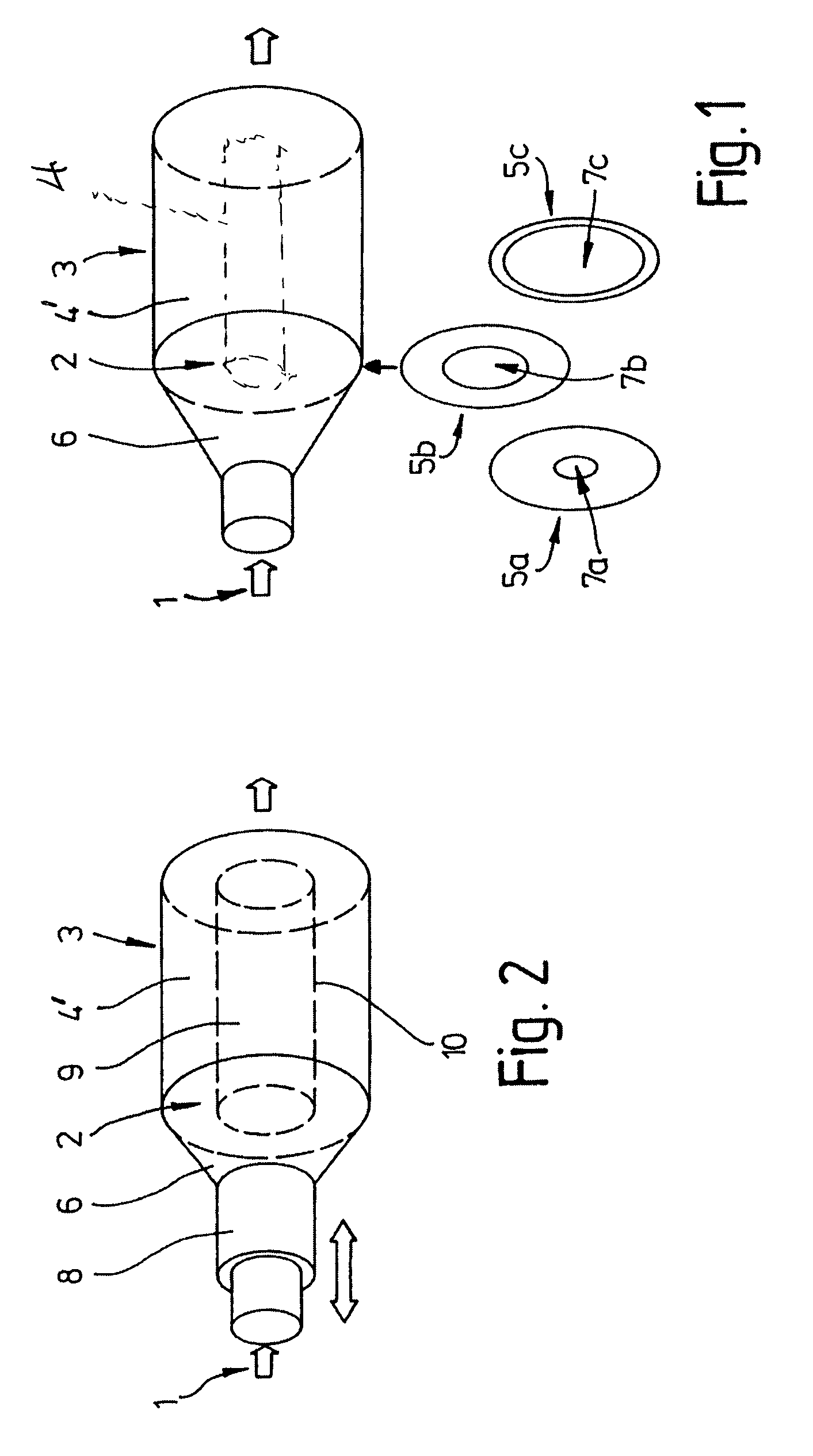
[0044]Two different embodiments of the invention are shown in FIGS. 1 and 2, in which means for adjusting a cross-sectional area 2 extending transversely to the flow direction of the operating medium stream 1, for example of a reformer or reforming unit, is provided. For example, in partial load operation in this case the operating medium stream 1 only acts on or only passes through an inner reactor volume 4 of the reformer 3 and / or the fixed bed reactor 4′, which is closest to its longitudinal axis.

[0045]Generally a reformer, gas purifying stage, burner or the like of an incompletely shown fuel cell system is not designed for maximum output, so that, for example, the flow during partial load operation is only about 1 / 10 of the flow during full load operation. Thus it is very greatly oversized in partial load operation. The heat loss during partial load operation is proportionally higher than in full load operation in the case of the prior art systems.

[0046]The reformer 3 according ...


PUM


Abstract

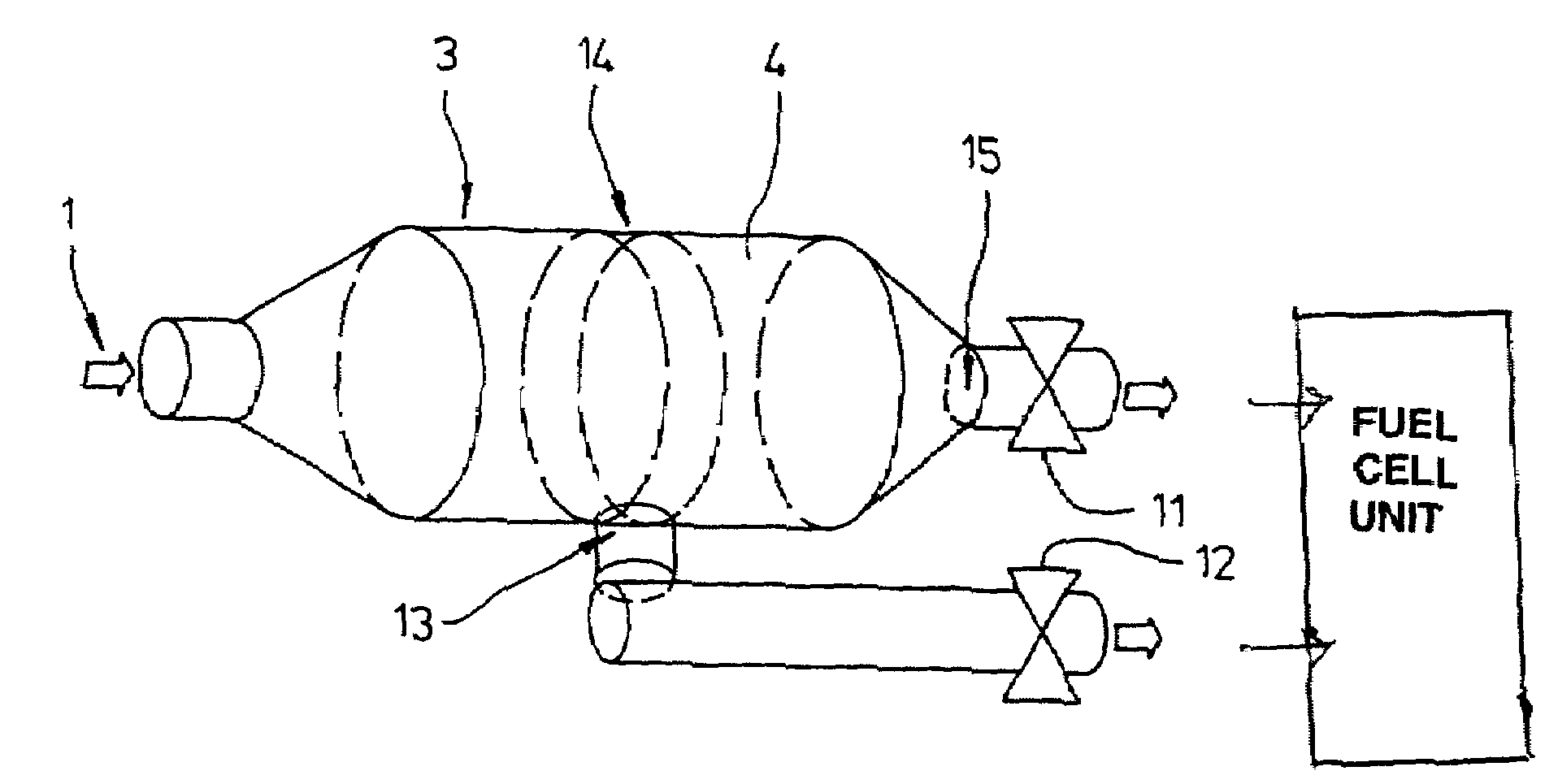
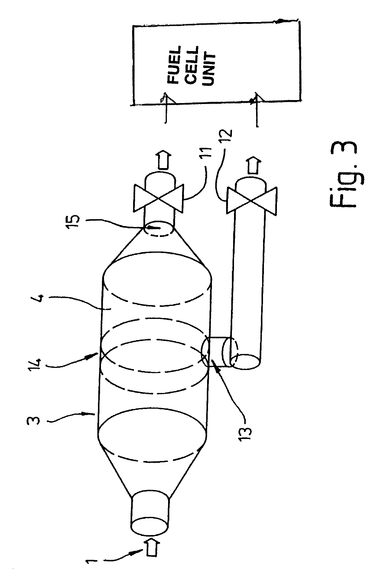
The fuel cell system has a fuel cell unit and a catalytically active reactor unit (3) for at least partial chemical transformation of an operating medium stream (1), especially a reformer, gas purifier stage and / or a combustor, in which the catalytically active reactor unit (3) has a variable catalytically active reactor volume (4) acted on by the operating medium stream. To provide the fuel cell system with a higher efficiency and good dynamic behavior the catalytically active reactor unit is provided with at least one control device (5, 8, 11, 12, 13) for controlling and / or for changing the variable catalytically active reactor volume (4) acted on by the operating medium stream (1). In a preferred embodiment the control device includes a first valve (11) for the reactor unit arranged downstream of the maximum reactor volume and a second valve (12) connected with the reactor unit upstream of the first valve, so that, when the second valve is opened and the first valve is closed, the operating medium stream (1) passes through an effective reactor volume that is smaller than the maximum reactor volume.

Description

BACKGROUND OF THE INVENTION[0001]1. Field of the Invention[0002]The present invention relates to a fuel cell system with a catalytically active reactor unit for at least partial chemical transformation of an operating medium stream, especially a reformer, gas purifier stage and / or a combustor, in which the catalytically active reactor unit has a catalytically active reactor volume acted on by the operating medium stream.[0003]2. Description of the Related Art[0004]Fuel cell technology is becoming ever more important, especially in connection with consumer-driven concepts for vehicles. Fuel cells offer the possibility to convert chemical energy directly to electrical energy, which subsequently can be converted into mechanical drive energy with the aid of an electrical motor.[0005]Because of technical problems with the hydrogen supply in vehicles the hydrogen must be produced, as needed, e.g. by a so-called reforming unit or partial oxidation of hydrocarbons, especially by means of a ...

Claims


Application Information

Patent Timeline
IPC IPC(8): H01M8/04H01M2/00H01M2/02H01M4/00H01M8/12B01J8/02B01J8/04B01J12/00B01J19/24C01B3/38H01M8/06
CPCB01J8/0214B01J8/0278B01J8/0415B01J8/0492B01J12/007B01J19/2485C01B3/38H01M8/0631B01J2208/025B01J2219/00166C01B2203/00C01B2203/0227C01B2203/066C01B2203/1011C01B2203/1035C01B2203/1064C01B2203/1276C01B2203/16H01M2250/20Y02E60/523Y02E60/50Y02T90/32Y02T90/40
Inventor FAYE, IANGOTTWICK, ULRICHSALIGER, RAINERGRAEHN, JAN-MICHAEL
Owner ROBERT BOSCH GMBH
Learn More