Optical filter element for devices for converting spectral information into location information

a technology of optical filter element and location information, which is applied in the direction of optical radiation measurement, instruments, spectrometry/spectrophotometry/monochromators, etc., can solve the problems of limited temporal resolution, excessive cost of respective applications, and large spatial extent, so as to prevent scattering effects and high surface quality

Active Publication Date: 2018-07-03
SENORICS GMBH
View PDF25 Cites 3 Cited by
  • Summary
  • Abstract
  • Description
  • Claims
  • Application Information

AI Technical Summary

Benefits of technology

[0032]The invention is based on the objective of disclosing an optical filter element for devices for converting spectral information into location information, wherein said filter element is suitably designed in such a way that its integration into spectroscopy or spectrometry devices in alignment with the light signal is realized in a space-saving fashion and therefore cost-effectively.DESCRIPTION
[0070]The band-pass filter of the inventive filter element is realized in such a way that a collimation takes place within the filter element and no other optical elements are required. In this way, particularly compact and cost-effective spectroscopic components and devices can be realized.
[0078]Both extensive surfaces (which are referred to as first surface and opposite second surface of the substrate below) are aligned plane-parallel to one another such that the thickness of the substrate is constant over the entire usable surface area. A high surface quality is furthermore advantageous in order to prevent scattering effects.

Problems solved by technology

Consequently, previous spectrometers are not suitable for all operating sites or the costs for the respective application are excessively high.
The above-described solutions have the disadvantage that an optical system, which is to some extent spatially extensive, or an additional component, which can only be manufactured with complex manufacturing technology, is required for obtaining suitable spectroscopic information from the combination of variable a band-pass filter and a detector.
One disadvantage of the two latter solutions can be seen in that the light signal to be analyzed has to be aligned as parallel as possible prior to its incidence in order to achieve an adequate resolution.
However, this device has the disadvantage that the frequency comb of the first microresonator does not allow a continuous spectrum during the measurement.
This also represents another disadvantage, wherein a measurement of a broad spectrum is only required in series such that the temporal resolution is limited.

Method used


Image

  • Optical filter element for devices for converting spectral information into location information
  • Optical filter element for devices for converting spectral information into location information
  • Optical filter element for devices for converting spectral information into location information

Examples


Embodiment Construction

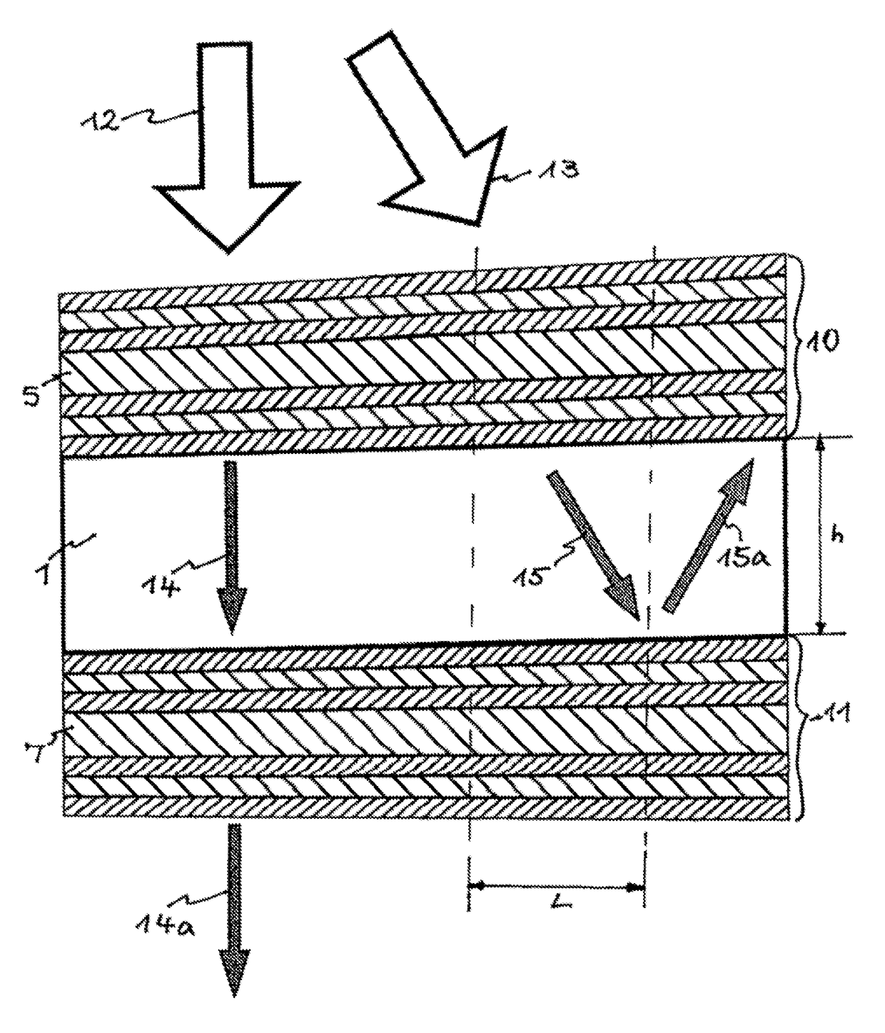
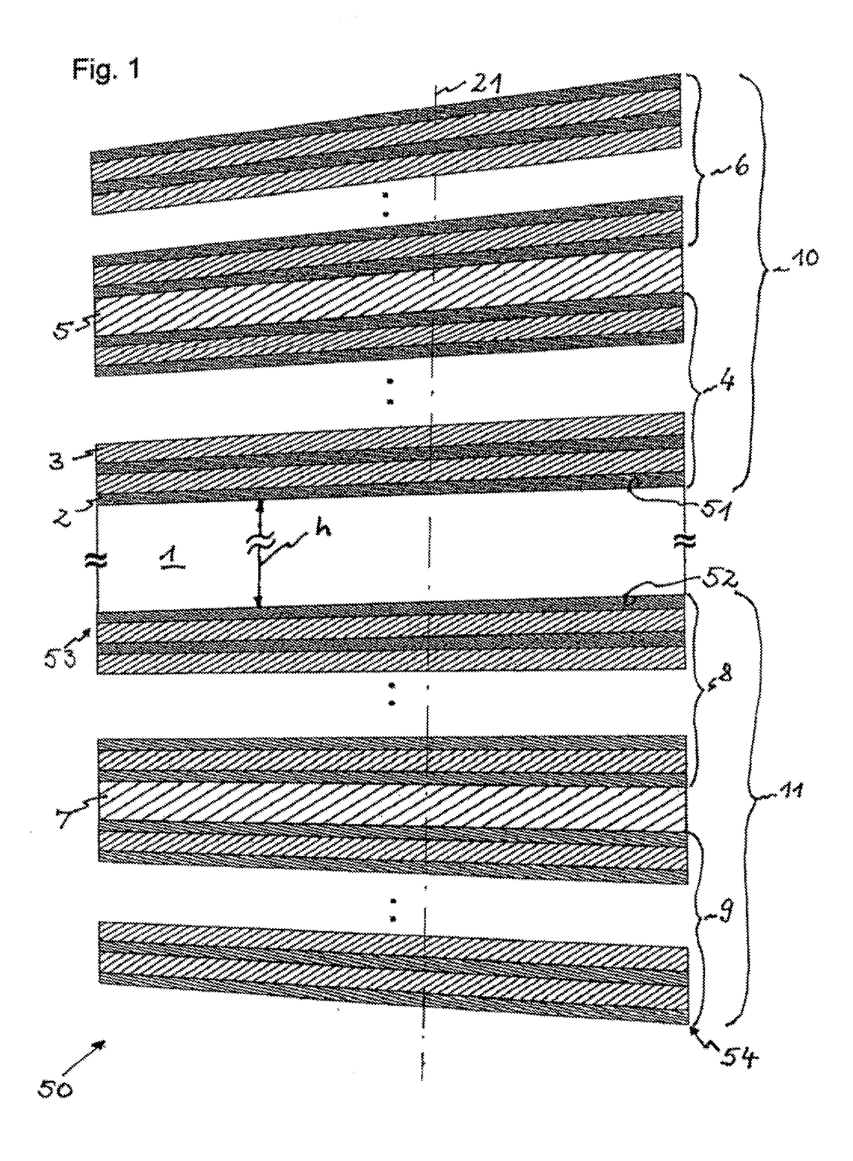
[0092]FIG. 1 schematically shows the design of an optical filter element 50, e.g., for a spectroscopic or spectrometric device for converting spectral information into location information.

[0093]The optical filter element 50 comprises at least two microresonators 10, 11, wherein a microresonator 10; 11 at least features[0094]at least two surface-covering reflective layer structures 4, 6; 8, 9 consisting of at least one material layer 2 with a high refractive index and at least one material layer 3 with a low refractive index in an alternating sequence, as well as[0095]at least one surface-covering resonance layer 5; 7 that is arranged between the two respective surface-covering reflective layer structures 4, 6; 8, 9.

[0096]According to the invention, the filter element 50 comprises at least a transparent, plane-parallel substrate 1 for optically decoupling the two microresonators 10, 11, wherein the first microresonator 10; 11 is located on a first of the two opposite surfaces 51; 52...


PUM


Abstract

An optical filter element for devices for converting spectral information into location information, uses a connected detector for detecting signals. The element has at least two microresonators, each comprising at least two superposed reflective layer structures of a material layer having a high refractive index and a material layer having a low refractive index in an alternating sequence, and at least one superposed resonance layer arranged between the two superposed reflective layer structures. The filter element comprises at least one transparent plane-parallel substrate for optically decoupling the two microresonators; the first microresonator being located on a first of two opposing surfaces of said substrate, and the second microresonator being located on said substrate on a second surface thereof that lies opposite the first surface. The resonance layer of at least one microresonator, and / or the reflective layer structure that surrounds said resonance layer, has a layer thickness which can vary along a horizontal axis of said filter element.

Description

CROSS REFERENCE TO RELATED APPLICATIONS[0001]This application is the National Phase filing under 35 U.S.C. § 371 of International Application No. PCT / DE2015 / 000504, filed on Oct. 7, 2015, and published on Apr. 14, 2016, as WO / 2016 / 055048 A1, and claims priority to German Application No. 102014014983.8, filed on Oct. 7, 2014. The contents of each of the prior applications are hereby incorporated by reference herein in their entirety.BACKGROUND ART[0002]The invention pertains to an optical filter element for devices for converting spectral information into location information with a connected detector for detecting signals, wherein said element comprises at least two microresonators, and wherein a microresonator at least features[0003]at least two surface-covering reflective layer structures consisting of at least one material layer with a high refractive index and at least one material layer with a low refractive index in an alternating sequence, as well as[0004]at least one surface...

Claims


Application Information

Patent Timeline
Patent Type & Authority Patents(United States)
IPC IPC(8): G01J3/32G01J3/02G01J3/26G01J3/28G02B5/28G01J3/12
CPCG01J3/26G01J3/0256G01J3/28G02B5/288G01J3/0289G01J2003/1234G01J3/2803G01J3/36
Inventor LANGNER, MAIKFROB, HARTMUTLYSSENKO, VADIM G.SUDZIUS, MARKASLEO, KARL
Owner SENORICS GMBH
Why Eureka
Try Eureka