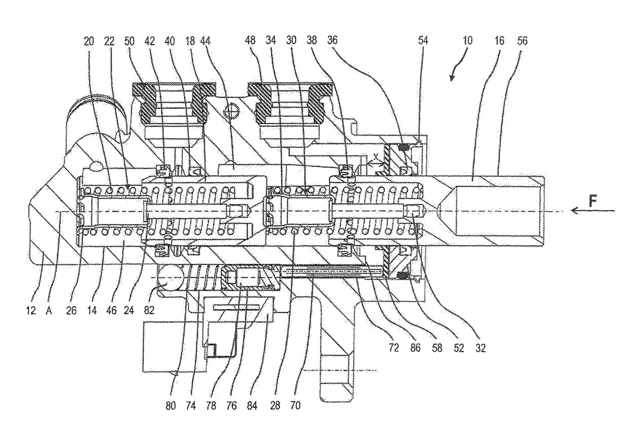
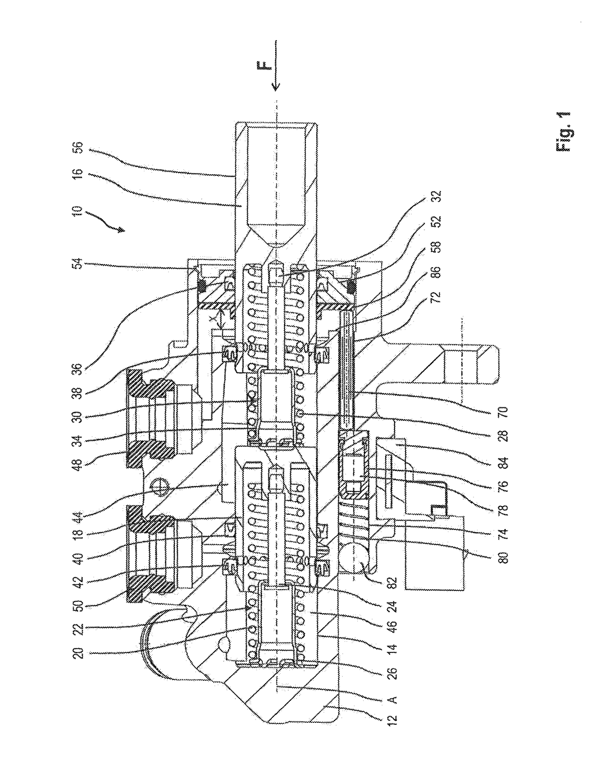
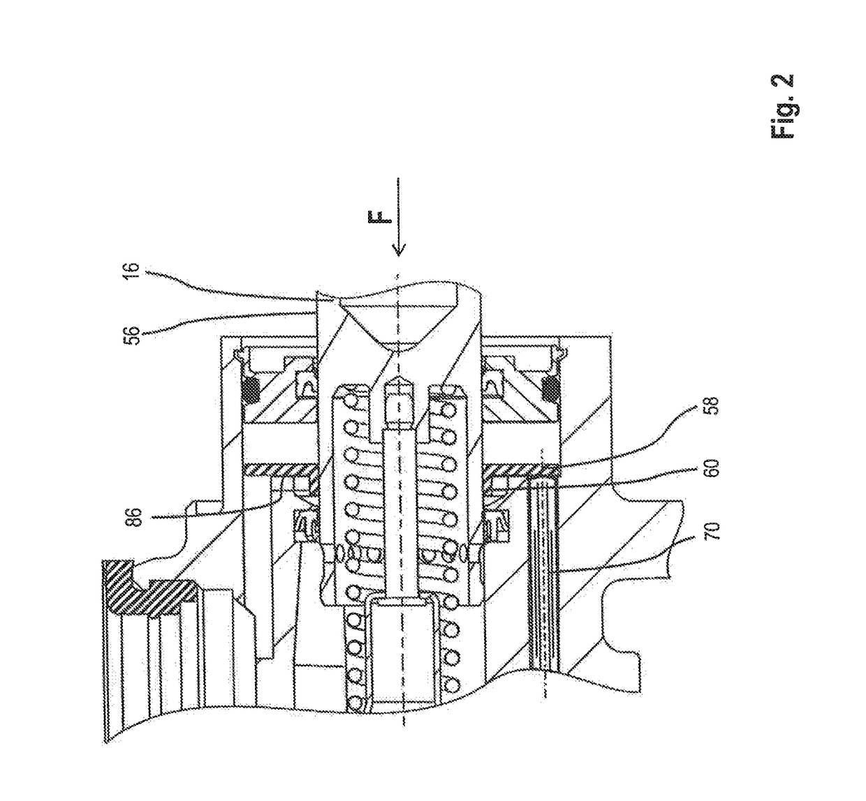
Master brake cylinder arrangement with actuation detection for a motor vehicle brake system
a technology of brake system and master cylinder, which is applied in the direction of brake action initiation, brake system, instruments, etc., can solve the problems of disadvantage, so to speak, of the coupling element from the piston, etc., and achieve the effect of reliable functioning, compact and cost-effectiv
- Summary
- Abstract
- Description
- Claims
- Application Information
AI Technical Summary
Benefits of technology
Problems solved by technology
Method used
Image
Examples
first embodiment
[0039]The from functioning regarding the position detection is the same as described above with reference to the
[0040]In FIGS. 5 and 6, a modification of the embodiment according to FIGS. 3 and 4 is shown. Once again, an initial position and an actuated position are illustrated. An essential difference from the embodiment according to FIGS. 3 and 4 is the provision of a diameter step 142 on the piston 16. The encircling end surface defined by the diameter step 142 and facing away from the base of the cylinder bore 14 serves as an abutment surface for the coupling element 58. A compression spring 140 is arranged between the coupling element 58 and the closure element 52 fixed to the housing. In the initial position shown in FIG. 5, the compression spring 140 is maximally compressed and biases the coupling element 58 against the diameter step 142. Analogously to the embodiment according to FIGS. 3 and 4, the coupling element after over-travelling of the predetermined distance abuts ag...
fifth embodiment
[0042]FIGS. 9 and 10 show the invention, wherein, to avoid repetitions and to facilitate the description, for components which have the same effect or are of the same kind, the same reference symbols are used as in the above description of the preceding embodiment. Once again, the initial position (FIG. 9) and an actuated position (FIG. 10) are shown.
[0043]In this fifth embodiment, the position detection rod 70 projects from the cylinder housing 12 in the axial direction A. The coupling element 58 in this embodiment is of pot-like and stepped configuration. It surrounds, on one side, the free right-hand end of the first piston 16 with its annular section 62 and the tubular section 68. Furthermore, it surrounds with a tubular extension 106 a plunger-like force input member 108, this tubular extension 106 being connected to the tubular section 68 via a bottom 110. The force input member 108 is of T-shaped configuration and accommodates in an accommodating section 114 a rubber body 112...
sixth embodiment
[0053]Compared with the sixth embodiment, the tubular section 132 of the holding bush 136 is configured with a markedly larger axial length, so that the annular section 138 is arranged axially spaced from the piston 16. Analogously to the previous examples, an actuating member (not shown) can be fastened in a known manner in the accommodating opening 120 of the piston 16 and extend along the longitudinal axis A through the holding bush 136.
[0054]In the embodiment shown, the coupling element 58 sectionally surrounds the tubular section 132 of the holding bush 136 with its tubular extension 106 and bears directly thereon. Thus, the coupling element 58 is dislocatably guided axially along the tubular section 132. In this case, a frictional engagement can also be provided between these elements or alternatively frictionless play.
[0055]The functioning of the arrangement from FIG. 13 corresponds essentially to that of the fifth and sixth embodiments described above. Accordingly, on exerti...
PUM
 Abstract
Description
Claims
Application Information
 - R&D
- Intellectual Property
- Life Sciences
- Materials
- Tech Scout
- Unparalleled Data Quality
- Higher Quality Content
- 60% Fewer Hallucinations
Browse by: Latest US Patents, China's latest patents, Technical Efficacy Thesaurus, Application Domain, Technology Topic, Popular Technical Reports.
© 2025 PatSnap. All rights reserved.Legal|Privacy policy|Modern Slavery Act Transparency Statement|Sitemap|About US| Contact US: help@patsnap.com


