Optical scanning apparatus and image forming apparatus equipped with the same
an image forming apparatus and scanning apparatus technology, applied in the direction of inking apparatus, instruments, electrographic processes, etc., can solve the problems of inability to reduce the size and cost of the image, the image density is uneven, and the image color density is uneven, so as to reduce the streaks in the image or the density of the image. , the effect of reducing the unevenness
- Summary
- Abstract
- Description
- Claims
- Application Information
AI Technical Summary
Benefits of technology
Problems solved by technology
Method used
Image
Examples
first embodiment
(First Embodiment)
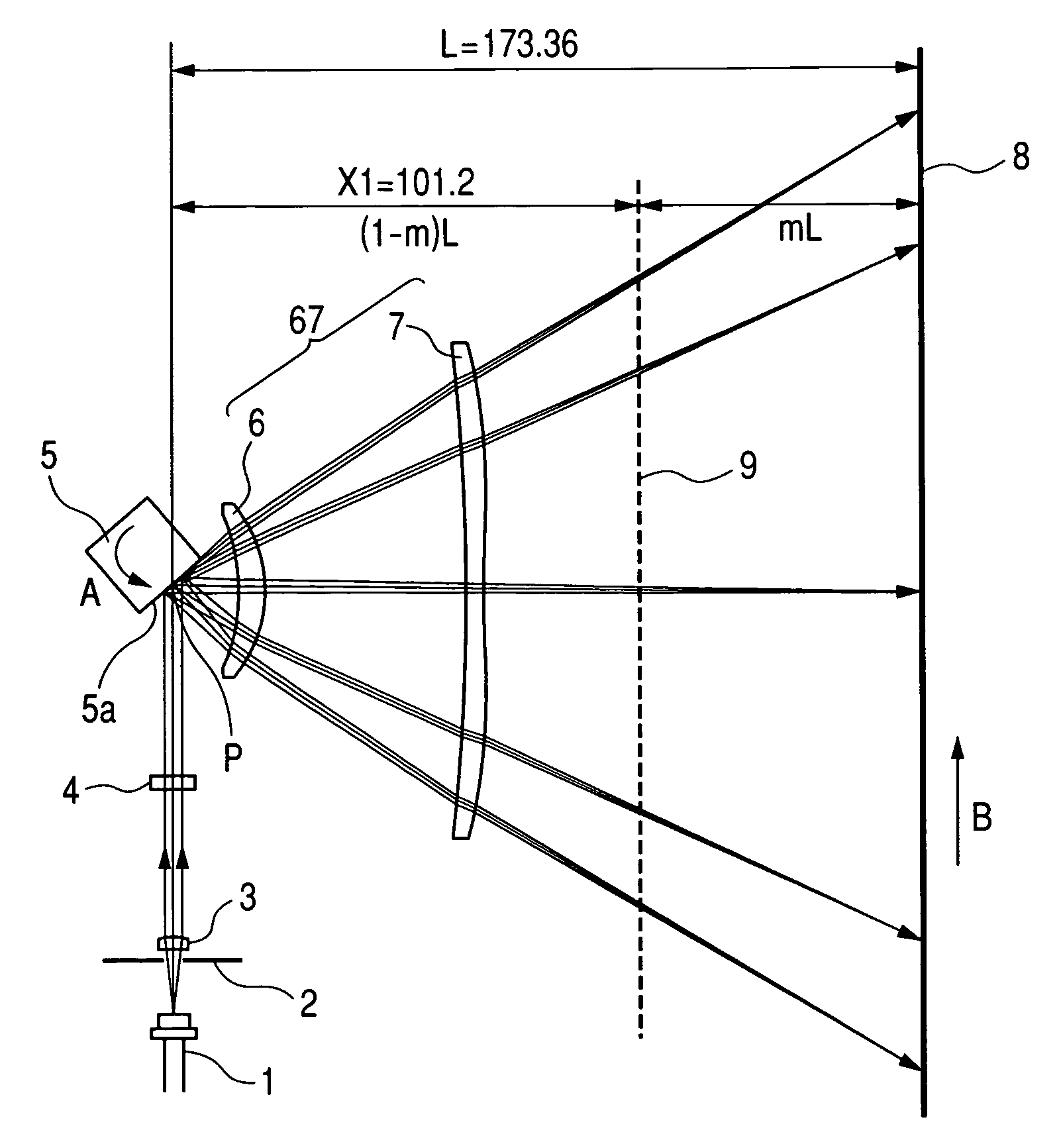
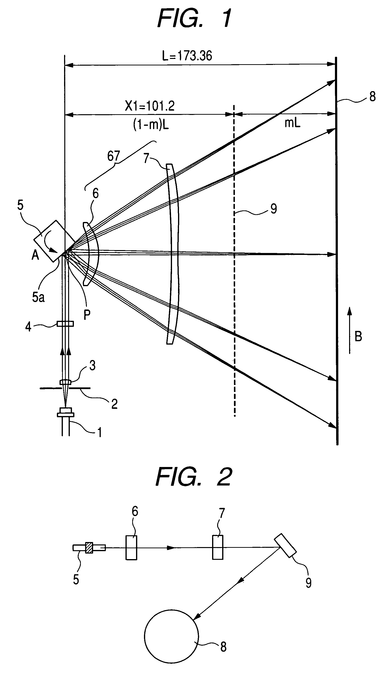
[0057]FIG. 1 is a cross sectional view taken on a main scanning cross section (in the main scanning direction) (or a main scanning cross sectional view) showing the principal portion of an optical scanning apparatus according to the first embodiment of the present invention. FIG. 2 is a cross sectional view taken on a sub-scanning cross section (in the sub-scanning direction) (or a sub-scanning cross sectional view) showing the principal portion of the optical scanning apparatus according to the first embodiment of the present invention.
[0058]Here, the main scanning direction refers to the direction orthogonal to the rotation axis of deflecting means and to the optical axis of a scanning optical element (that is, the direction in which the light beam is reflected and deflected (or deflected and scanned)), and the sub-scanning direction refers to the direction parallel to the rotation axis of the deflecting means. The main scanning cross section refers to the plane ...
second embodiment
(Second Embodiment)
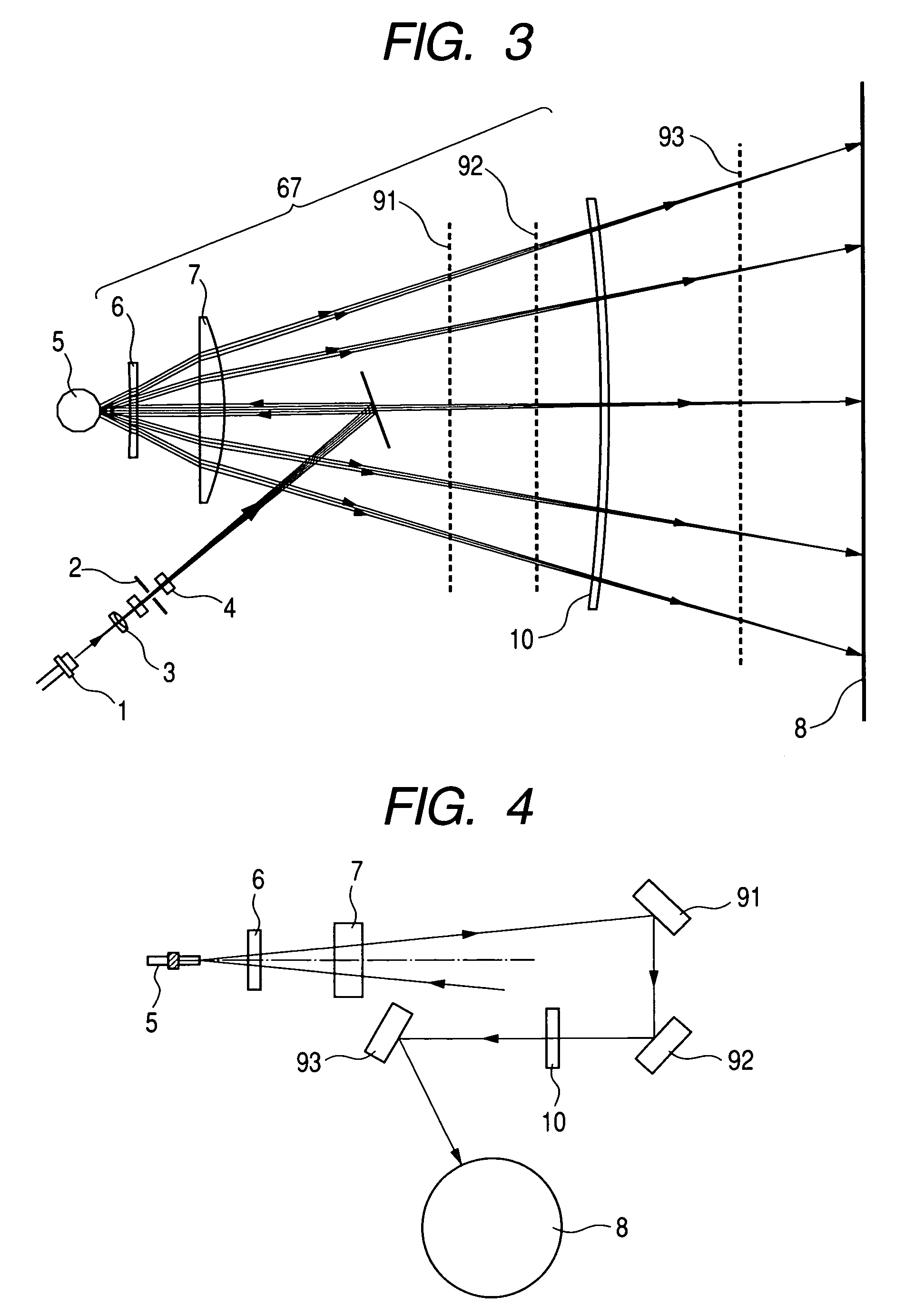
[0092]FIG. 3 is a cross sectional view in the main scanning direction (or a main scanning cross section) showing the principal portion of the second embodiment of the present invention. FIG. 4 is a cross sectional view in the sub-scanning direction (or a sub-scanning cross section) showing the principal portion of the second embodiment of the present invention. In FIGS. 3 and 4, elements the same as those shown in FIGS. 1 and 2 are designated by the same reference numerals.
[0093]What is different in this embodiment from the above-described first embodiment is that the incidence optical system is composed of an overfilled scanning optical system (OFS) and that the reflection means is composed of three turn back mirrors 91, 92 and 93. The other structures and optical functions are substantially the same as those in the first embodiment, and the same advantageous effects are achieved by them.
[0094]Specifically, in this embodiment, a light beam emitted from the light ...
third embodiment
(Third Embodiment)
[0110]FIG. 6 is a cross sectional view in the main scanning direction (or a main scanning cross sectional view) showing the principal portion of the third embodiment of the present invention. FIG. 7 is a cross sectional view in the sub-scanning direction (or a sub-scanning cross sectional view) showing the principal portion of the third embodiment of the present invention. In FIGS. 6 and 7, elements the same as those shown in FIGS. 1 and 2 are designated by the same reference numerals.
[0111]What is different in this embodiment from the first embodiment described before is that the diameter of an aperture stop 82 is configured so that set the spot size in the main scanning cross section is set to 30 μm and the spot size in the sub-scanning cross section is set to 35 μm and that the reflecting means is composed of two turn back mirrors 91 and 92. The other structures and optical functions are substantially the same as those in the first embodiment, and the same advan...
PUM
 Abstract
Description
Claims
Application Information
 - R&D
- Intellectual Property
- Life Sciences
- Materials
- Tech Scout
- Unparalleled Data Quality
- Higher Quality Content
- 60% Fewer Hallucinations
Browse by: Latest US Patents, China's latest patents, Technical Efficacy Thesaurus, Application Domain, Technology Topic, Popular Technical Reports.
© 2025 PatSnap. All rights reserved.Legal|Privacy policy|Modern Slavery Act Transparency Statement|Sitemap|About US| Contact US: help@patsnap.com


