Packet processing engine architecture

a processing engine and engine technology, applied in the field of packet processing, can solve the problems of reducing reducing and using a relatively large amount of processor resources, so as to reduce the amount of data, reduce the number of pins required, and reduce the amount of information exchanged

Inactive Publication Date: 2007-05-15
CISCO TECH INC
View PDF36 Cites 94 Cited by
  • Summary
  • Abstract
  • Description
  • Claims
  • Application Information

AI Technical Summary

Benefits of technology

[0015]In a second aspect of the invention, the PPE and the FFE each have separate hardware resources allocated to their functions; these separate hardware resources can include pin count, on chip memory, and transfer bandwidth to off-chip memory. This allows the PPE and the FFE to each perform their functions in parallel without substantial contention for operating resources.
[0017]In a preferred embodiment, the PPE includes separate treatment of packet header information and payload information, so the amount of information exchanged between the PPE and the FFE, and the amount of actual data movement performed by the PPE, can be relatively minimized. When determining the packet header information, the PPE can also parse the data packet (particularly what is conventionally called the packet header) and extract fields needed by the FFE to perform it's forwarding, ACL and QoS decisions. In this way, the PPE reduces the amount of data that it needs to transmit to the FFE, thereby reducing the number of pins required by both the PPE and the FFE to implement this communication.

Problems solved by technology

One problem in the known art is that the lookup operation can be relatively complex, and can use a relatively large amount of processor resources.
While these responses achieve the goal of routing messages in a forwarding network, they have the disadvantage that added services introduce additional load on the router processor and slow down the router.

Method used


Image

  • Packet processing engine architecture
  • Packet processing engine architecture
  • Packet processing engine architecture

Examples


Embodiment Construction

[0021]In the following description, a preferred embodiment of the invention is described with regard to preferred process steps and data structures. Those skilled in the art would recognize after perusal of this application that embodiments of the invention can be implemented using circuits adapted to particular process steps and data structures described herein, and that implementation of the process steps and data structures described herein would not require undue experimentation or further invention.

[0022]System Elements

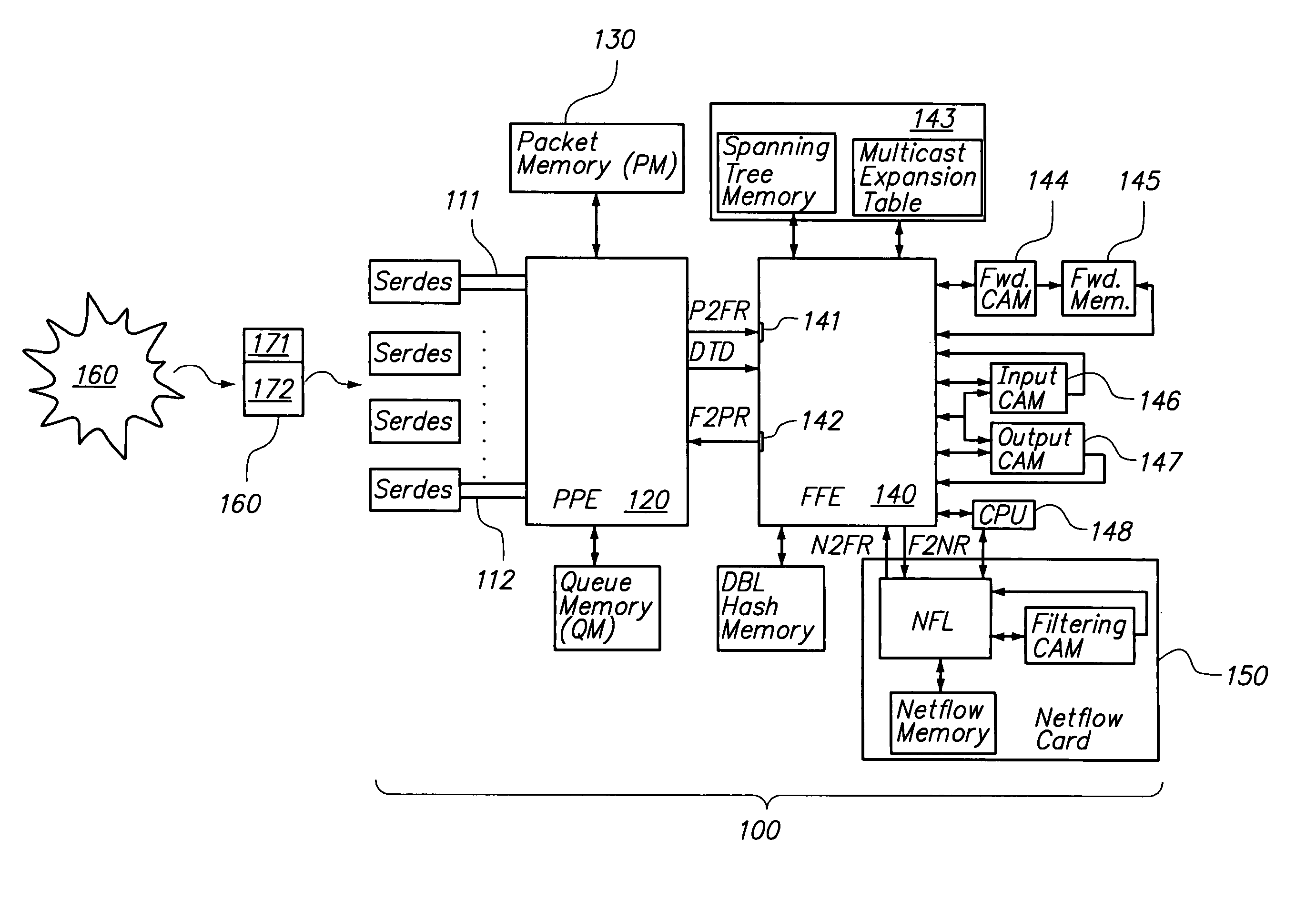
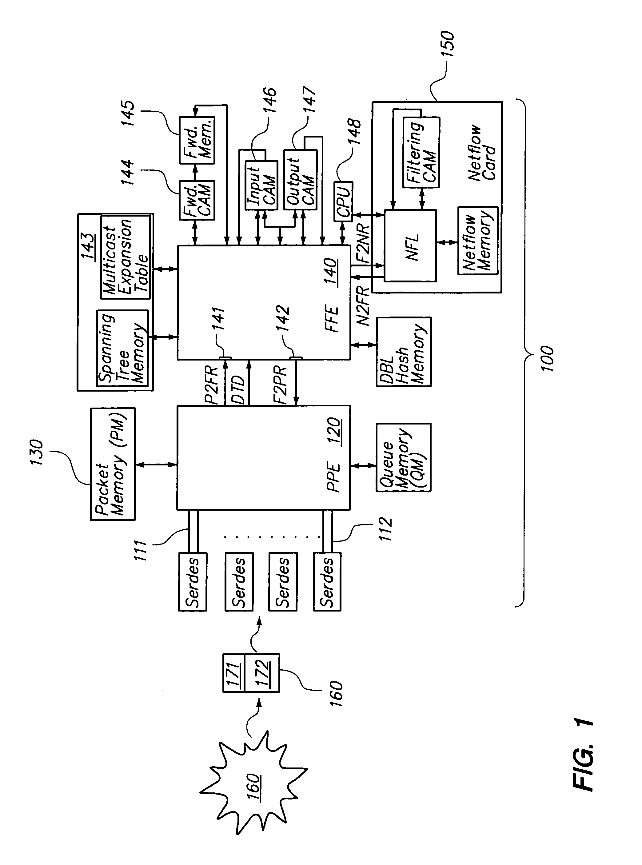
[0023]FIG. 1 shows a block diagram of a system for packet processing and packet forwarding.

[0024]A router 100 includes a set of input interfaces 111, a set of output interfaces 112, a packet processing engine (PPE) 120, a PPE memory 130, and a fast forwarding engine (FFE) 140. The router 100 is coupled to one or more communication networks 160. In one embodiment, PPE 120 comprises a single monolithic semiconductor circuit. In one embodiment, FFE 140 comprises sin...


PUM


Abstract

The invention provides a method and system for packet processing, in which a router (or switch) is capable of quickly processing incoming packets, thus performing level 2, 3, and 4 routing and additional services, in real time. A system includes a packet processing engine (PPE), having elements for receiving packets, distinguishing header and payload information for those packets, outsourcing router decision-making to additional hardware resources such as a fast forwarding engine (FFE), and forwarding those packets. The PPE is synchronized to the FFE, so that the PPE can send and the FFE can receive packets at each one of a sequence of constant-duration time quanta. Similarly, the PPE can receive and the FFE can send packet routing information at each one of a sequence of similar time quanta. The PPE and the FFE have separate hardware so that their functions can be performed in parallel without contention for operating resources.

Description

BACKGROUND OF THE INVENTION[0001]1. Field of the Invention[0002]This invention relates to packet processing.[0003]2. Related Art[0004]In a computer network for transmitting information, messages are received by each router (or switch) at an input interface and retransmitted at an output interface, so as to forward those messages onward to their respective destinations. Each router performs a lookup operation for each message it encounters, in which the router determines from the message to which output interface the message should be forwarded.[0005]One problem in the known art is that the lookup operation can be relatively complex, and can use a relatively large amount of processor resources. For example, the lookup operation can be complicated by concurrently determining one or more of the following:[0006]which output interface is the closest, within a defined network topology, to the specified destination;[0007]whether the message is unicast or multicast, and in the latter case, ...

Claims


Application Information

Patent Timeline
Patent Type & Authority Patents(United States)
IPC IPC(8): H04L12/28
CPCH04L45/60H04L45/7453H04L49/3009H04L49/25H04L49/254
Inventor BECHTOLSHEIM, ANDREAS V.CHERITON, DAVID R.
Owner CISCO TECH INC
Why Eureka
Try Eureka