Computer aided detection (CAD) for 3D digital mammography

a computer-aided detection and digital mammography technology, applied in the field of digital imaging analysis, can solve the problems of film saturation, hinder the clinician's ability to properly identify, and the standard mammography technique suffers from many problems, so as to achieve the effect of reducing contrast, reducing contrast, and reducing contras

Active Publication Date: 2007-05-15
GENERAL ELECTRIC CO
View PDF38 Cites 82 Cited by
  • Summary
  • Abstract
  • Description
  • Claims
  • Application Information

AI Technical Summary

Benefits of technology

[0005]One problem with film based mammography can be generally referred to as film saturation. To fully penetrate through dense parts of the breast, a higher dose of radiation is utilized, generally on the order of about 3 Gy. In relatively dense parts of the breast, a sizeable amount of the radiation is absorbed by the dense tissue, the residual radiation exposing the film. Due to the large x-ray absorption within the dense tissue, the film is not saturated by too much re...

Problems solved by technology

These standard mammography techniques, however, suffer from many problems.
Near the edges of the breast (e.g. near the skin surface), however, the higher dose of radiation is absorbed to a lesser extent, thus a higher amount of residual radiation exposes the film, which results in film saturation.
Film saturation can lead to lower contrast (if any at all) especially near the edges of the breast, and may hinder the clinician's ability to properly identify an abnormality.
Furthermore, the 2D nature of standard mammography techniques (including standard digital and film based) also leads to superposition (e.g., overlay) problems.
The overlaid normal (i.e., non-malignant) structures may end up combining in appearance to appear as an abnormality, resulting in a “false positive” identification of an abnormality.
Conversely, real abnormalities may be superimposed over dense tissue regions which “hide” the abnormality within the dense tissue, resulting in a “false negative” miss of an abnormality.
Thus, in standard 2D imaging (e.g., projection radiography) structures within the breast may become superimposed with each other, thereby normal structures within the breast can “interfere” with a clear interpretation of structures of interest (e.g., potentially malignant) which are located at a different height (relative to the projection dir...

Method used


Image

  • Computer aided detection (CAD) for 3D digital mammography
  • Computer aided detection (CAD) for 3D digital mammography
  • Computer aided detection (CAD) for 3D digital mammography

Examples


Embodiment Construction

[0027]Reference will now be made in detail to presently preferred embodiments of the present invention. Wherever possible, the same reference numbers will be used throughout the drawings to refer to the same or like parts.

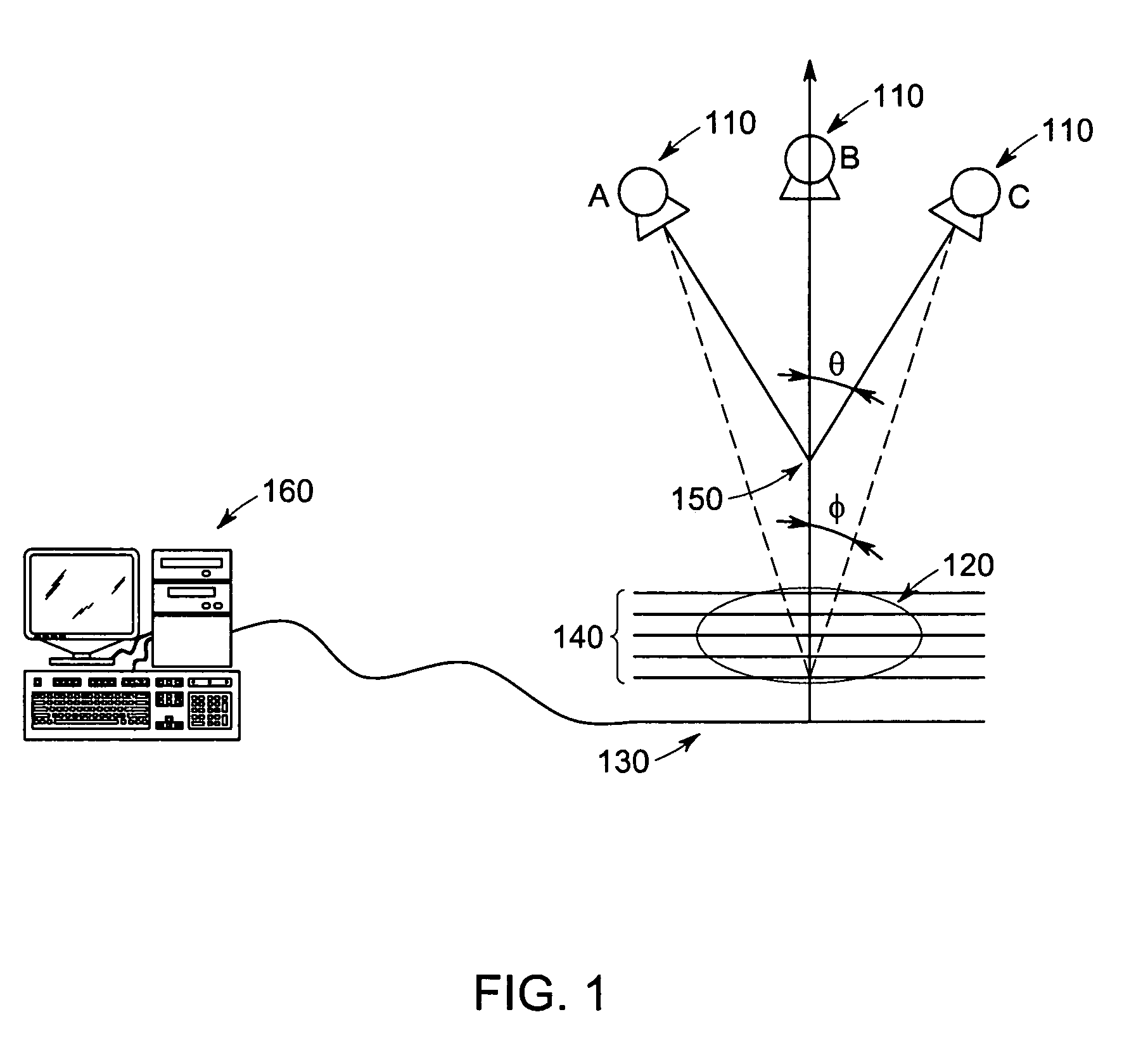
[0028]The present invention will be described in reference to apparatuses and methodology for breast imaging and breast cancer detection. It should be appreciated, however, that the teachings of the present invention may also be used in other areas, such as lung imaging, brain imaging, liver imaging, kidney imaging, bone imaging, and other medical areas, as well as in industrial applications, such as detecting low density regions in fabricated parts, or performing fault / fatigue testing (e.g., examining for cracks, depressions, or impurities).

[0029]In recent years, research into improved imaging systems for breast cancer detection has focused on digital imaging systems, and more particularly, to digital imaging systems with automated abnormality detection and risk...


PUM


Abstract

There is provided a method of analyzing a plurality of views of an object, the object including an edge portion partially extending from a surface of the object into an internal volume of the object, comprising the step of analyzing each acquired view. The step of analyzing each acquired view includes analysis of the edge portion. Preferably, the object comprises breast tissue.

Description

STATEMENT REGARDING FEDERALLY SPONSORED RESEARCH & DEVELOPMENT[0001]The government may have rights in this invention pursuant to Subcontract 22287 issued from the Office of Naval Research / Henry M. Jackson Foundation.BACKGROUND OF THE INVENTION[0002]The present invention relates generally to analyzing digital imaging, and more particularly to computer aided detection (CAD) of abnormalities in a three dimensional (3D) mammography method, system, and apparatus.[0003]It is well know in the medical community that breast cancer is a leading cause of death in women (and to a lesser extent also affects men). When early detection of abnormalities is combined with proper medical attention, however, the risk of death and / or severe medical ramifications can be drastically reduced. Many devices and techniques (e.g., mammography) are currently under development to detect breast abnormalities earlier, and with greater accuracy than conventional devices. A brief summary of some conventional devices...

Claims


Application Information

Patent Timeline
IPC IPC(8): G06K9/00A61B6/00A61B6/03G06T7/00G06T19/00
CPCA61B6/463A61B6/466A61B6/502A61B6/5247A61B8/463G06T7/0012A61B6/03G06T2207/30068Y10S128/922
Inventor EBERHARD, JEFFREY WAYNEALYASSIN, ABDALMAJEID MUSAKAPUR, AJAY
Owner GENERAL ELECTRIC CO
Why Eureka
Try Eureka