System and method for communicating optical signals to multiple subscribers having various bandwidth demands connected to the same optical waveguide
Inactive Publication Date: 2007-05-15
ARRIS SOLUTIONS
160 Cites 38 Cited by
AI-Extracted Technical Summary
Problems solved by technology
One problem faced by many conventional optical network architectures is servicing subscribers that have various degrees or levels of demand for bandwidth.
Such conventional optical network architectures using separate fiber optic cables for each customer because of bandwidth concerns adds to the complexity as well as the cost of such a system since separate hardware and software components are usually required to service two different fiber optic cables.
Unrelated to the multiple service/multiple bandwidth problems faced by many conventional optical network architectures, another problem faced by optical network architectures is the attenuation of video service signals.
Specifically, when analog video optical signals are converted to the electrical domai...
View moreBenefits of technology
[0020]The multi-subcriber optical interface is but one part of the present invention. The present invention also comprises an efficient coupler, referred to as an optical tap, between a laser transceiver node and a respective single or multi-subscriber optical interface. The optical tap can divide optical signals between a plurality of subscribers and can be simple in its design. For example, each optical tap can comprise an optical splitter that may feed one or more subscribers. Optical taps can be cascaded or they can be connected in a star architecture from t...
View moreAbstract
The present invention is generally drawn to optical network architecture that can include a multi-subscriber optical interface that can service a plurality of subscribers that are located in close proximity relative to one another. For example, the multi-subscriber optical interface can service multiple dwelling units such as an apartment complex that has many different subscribers to the optical network system. Further, the invention can also service subscribers over the same optical waveguide who may have different bandwidth needs, such as businesses, personal/home users and the like.
Application Domain
Technology Topic
Image
Examples
- Experimental program(1)
Example
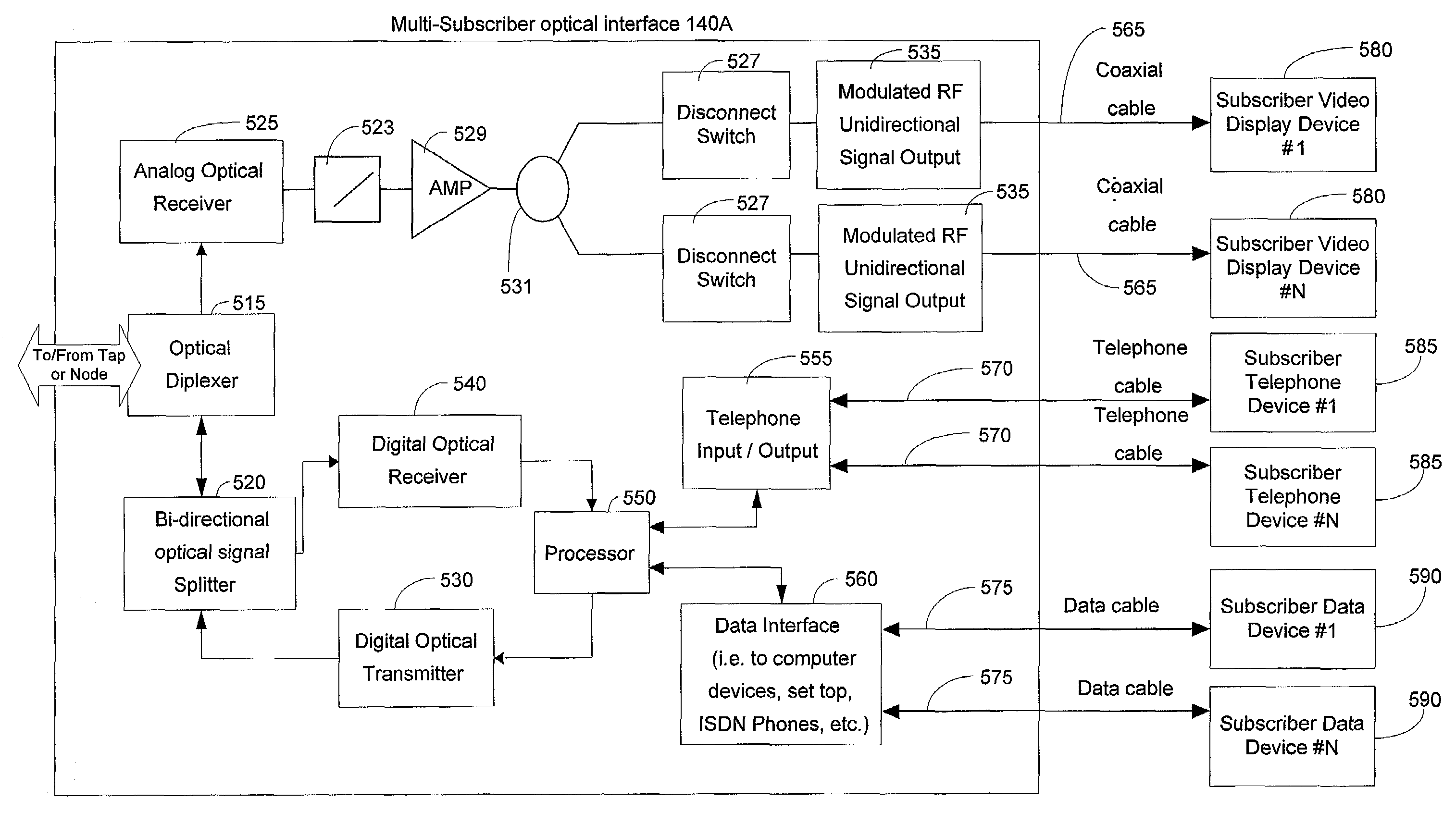
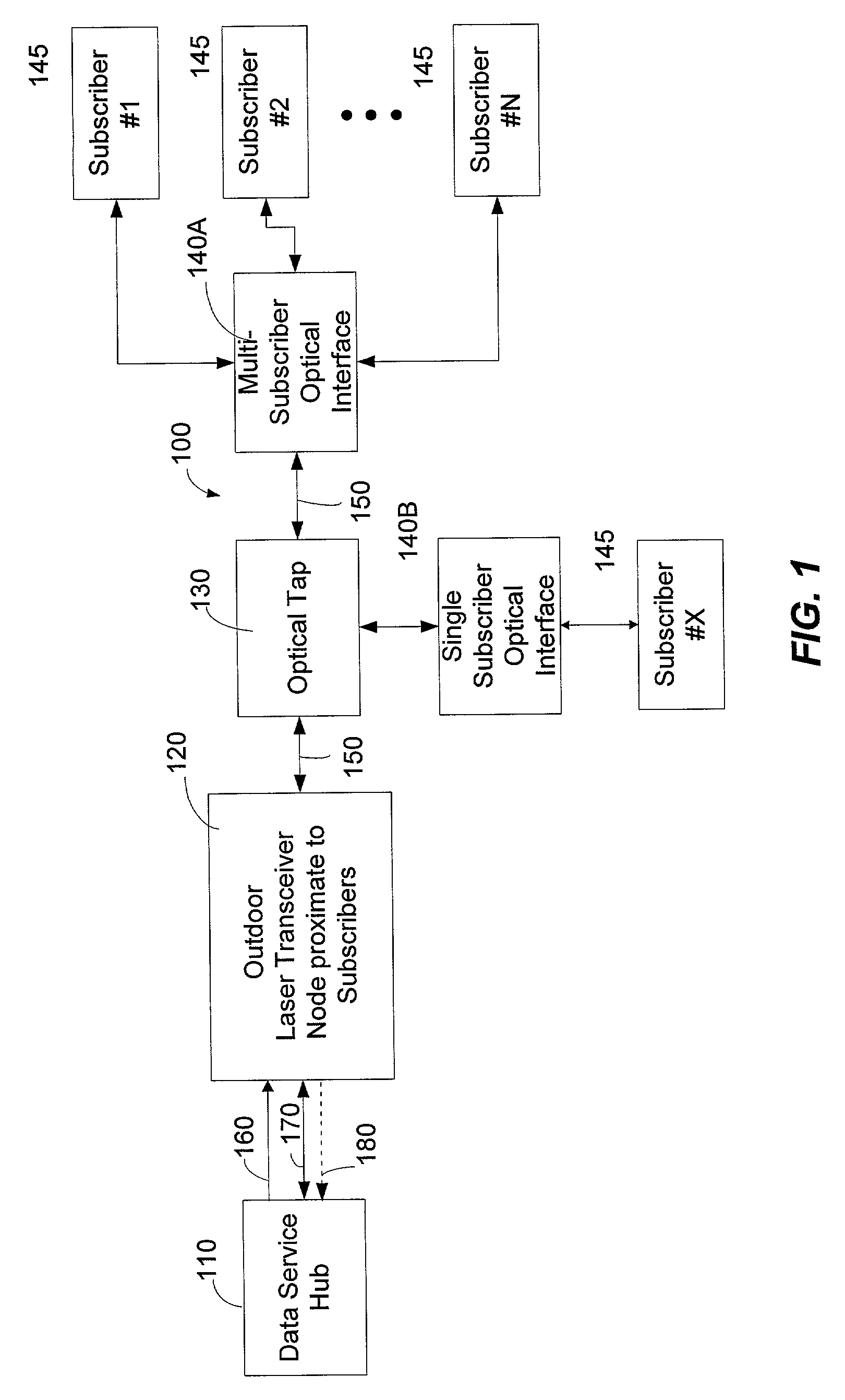
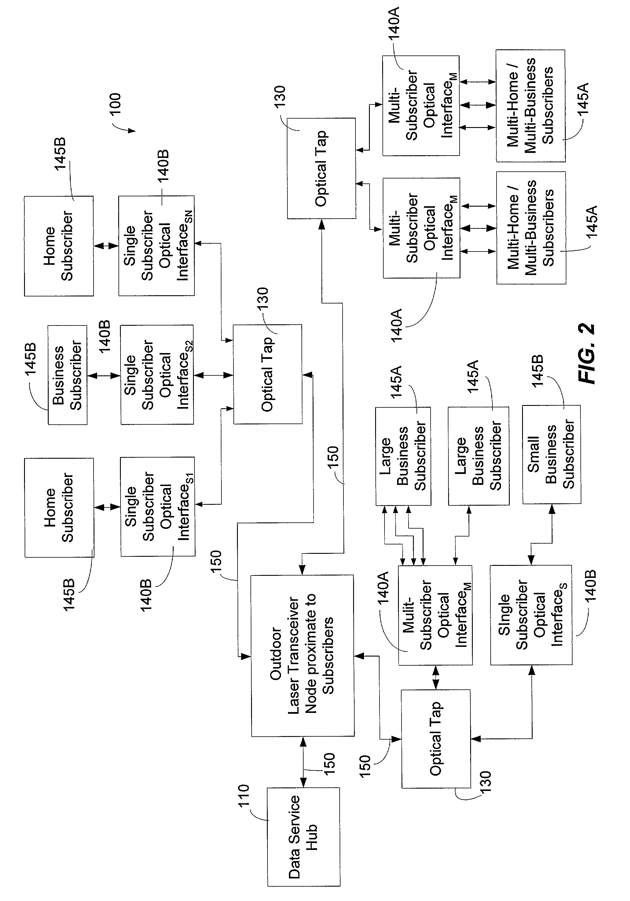
[0044]An optical network architecture according to the present invention can include a multi-subscriber optical interface that can service a plurality of subscribers that are located in very close proximity relative to one another. For example, the multi-subscriber optical interface can service multiple dwelling units such as an apartment complex that has many different subscribers of the optical network system. In addition to servicing multiple subscribers that are located in very close proximity relative to one another, the present invention can also service many different types of subscribers with the same multi-subscriber optical interface. That is, the multi-subscriber optical interface can service personal-use subscribers with relatively modest bandwidth demand while servicing businesses that may have relatively high bandwidth demand.
[0045]The multi-subscriber optical interface can be part of an optical network system that also employs single subscriber optical interfaces. In other words, the multi-subscriber optical interface can be combined with a single subscriber optical interfaces that are designed to handle the optical communications for a single subscriber to the network.
[0046]Referring now to the drawings, in which like numerals represent like elements throughout the several Figures, aspects of the present invention and the illustrative operating environment will be described.
[0047]FIG. 1 is a functional block diagram illustrating an exemplary optical network architecture 100 according to the present invention. The exemplary optical network architecture 100 comprises a data service hub 110 that is connected to one or more outdoor laser transceiver nodes 120. The laser transceiver nodes 120, in turn, are connected to an optical taps 130. The optical taps 130 can be connected to a plurality of subscriber optical interfaces 140. Specifically, the optical taps 130 maybe connected to one or more multi-subscriber optical interfaces 140A or single subscriber optical interfaces 140B or a combination thereof. Subscribers 145 can be connected to each of the respective subscriber optical interfaces 140.
[0048]Between respective components of the exemplary optical network architecture 100 are optical waveguides such as optical waveguides 150, 160, 170 and 180. The optical waveguides 150–180 are illustrated by arrows with the arrowheads of the arrows illustrating exemplary directions of the data flow between respective components of the illustrative an exemplary optical network 100.
[0049]While only an individual laser transceiver nodes 120, individual optical taps 130, and individual subscriber optical interfaces 140 are illustrated in FIG. 1, as will become apparent from FIG. 2, in its corresponding description, a plurality of laser transceiver nodes 120, optical taps 130, and subscriber optical interfaces 140 can be employed without departing from the scope and spirit of the present invention. Typically, many of the exemplary embodiments of the present invention, multiple subscriber optical interfaces 140 are connected to one or more optical taps 130.
[0050]The outdoor laser transceiver node 120 can allocate additional or reduced bandwidth based upon the demand of one or more subscribers that use the subscriber optical interfaces 140. The outdoor laser transceiver node 120 can be designed to withstand outdoor environmental conditions and can be designed to hang on a strand or fit in a pedestal or “hand hole.” The outdoor laser transceiver node can operate in a temperature range between minus 40 degrees Celsius to plus 60 degrees Celsius. The laser transceiver node 120 can operate in this temperature range by using passive cooling devices that do not consume power.
[0051]In one exemplary embodiment of the present invention, three trunk optical waveguides 160, 170, and 180 (that can comprise optical fibers) can conduct optical signals from the data service hub 110 to the outdoor laser transceiver node 120. It is noted that the term “optical waveguide” used in the present application can apply to optical fibers, planar light guide circuits, and fiber optic pigtails and other like optical waveguides.
[0052]A first optical waveguide 160 can carry broadcast video and other signals. The signals can be carried in a traditional cable television format wherein the broadcast signals are modulated onto carriers, which in turn, modulate an optical transmitter (not shown) in the data service hub 110. A second optical waveguide 170 can carry downstream targeted services such as data and telephone services to be delivered to one or more subscriber optical interfaces 140. In addition to carrying subscriber-specific optical signals, the second optical waveguide 170 can also propagate internet protocol broadcast packets, as is understood by those skilled in the art.
[0053]In one exemplary embodiment, a third optical waveguide 180 can transport data signals upstream from the outdoor laser transceiver node 120 to the data service hub 110. The optical signals propagated along the third optical waveguide 180 can also comprise data and telephone services received from one or more subscribers. Similar to the second optical waveguide 170, the third optical waveguide 180 can also carry IP broadcast packets, as is understood by those skilled in the art.
[0054]The third or upstream optical waveguide 180 is illustrated with dashed lines to indicate that it is merely an option or part of one exemplary embodiment according to the present invention. In other words, the third optical waveguide 180 can be removed. In another exemplary embodiment, the second optical waveguide 170 propagates optical signals in both the upstream and downstream directions as is illustrated by the double arrows depicting the second optical waveguide 170.
[0055]In such an exemplary embodiment where the second optical waveguide 170 propagates bi-directional optical signals, only two optical waveguides 160, 170 would be needed to support the optical signals propagating between the data server's hub 110 in the outdoor laser transceiver node 120. In another exemplary embodiment (not shown), a single optical waveguide can be the only link between the data service hub 110 and the laser transceiver node 120. In such a single optical waveguide embodiment, three different wavelengths can be used for the upstream and downstream signals. Alternatively, bi-directional data could be modulated on one wavelength.
[0056]In one exemplary embodiment, the optical tap 130 can comprise an 8-way optical splitter. This means that the optical tap 130 comprising an 8-way optical splitter can divide downstream optical signals eight ways to serve eight different subscriber optical interfaces 140. In the upstream direction, the optical tap 130 can combine the optical signals received from the eight subscriber optical interfaces 140.
[0057]In another exemplary embodiment, the optical tap 130 can comprise a 4-way splitter to service four subscriber optical interfaces 140. Yet in another exemplary embodiment, the optical tap 130 can further comprise a 4-way splitter that is also a pass-through tap meaning that a portion of the optical signal received at the optical tap 130 can be extracted to serve the 4-way splitter contained therein while the remaining optical energy is propagated further downstream to another optical tap or another subscriber optical interface 140. The present invention is not limited to 4-way and 8-way optical splitters. Other optical taps having fewer or more than 4-way or 8-way splits are not beyond the scope of the present invention.
[0058]Referring now to FIG. 2, this figure is a functional block diagram illustrating an exemplary optical network architecture 100 that includes various types of subscribers 145. Specifically, one type of a subscriber can comprise a large business subscriber or a multi dwelling or multiple business subscribers 145A. Another type of subscriber can comprise a home or personal-use or small business subscriber 145B. The terms “large” and “small” are defined relative to the amount of bandwidth needed or demanded by a particular subscriber 145.
[0059]Each optical tap 130 can comprise an optical splitter. The optical tap 130 allows multiple subscriber optical interfaces 140 (such as single subscriber optical interfaces 140B or multiple or multi-subscriber optical interfaces 140A) to be coupled to a single optical waveguide 150 that is connected to the outdoor laser transceiver nodes 120. In one exemplary embodiment, six optical fibers 150 are designed to be connected to the outdoor laser transceiver nodes 120. For the use of optical taps 130, sixteen subscribers can be assigned to each of the six optical waveguides 150 that are connected to the outdoor laser transceiver nodes 120.
[0060]In another exemplary embodiment, twelve optical fibers 150 can be connected to the outdoor laser transceiver nodes 120 while eight subscriber optical interfaces 140 are assigned to each of the twelve optical waveguides 150. Those skilled in the art will appreciate the number of subscriber optical interfaces 140 assigned to a particular waveguide 150 that is connected between the outdoor laser transceiver nodes 120 and a subscriber optical interface 140 (by way of the optical tap 130) can be varied or changed without departing from the scope and spirit of the present invention. Further, those skilled in the art recognize that the actual number of subscriber optical interfaces 140 assigned to a particular optical waveguide is dependent upon the amount of power available on a particular optical waveguide 150.
[0061]As depicted in FIG. 2, many configurations for supplying communication services to subscribers are possible. Combinations of single subscriber optical interfaces 140B coupled with multiple subscriber optical interfaces 140A along the same the optical waveguide is possible with the present invention. The combinations of optical taps 130 with other optical taps 130 in addition to combinations of optical taps with various types of subscriber optical interfaces 140 are limitless. With the optical taps 130, concentrations of distribution optical waveguide 150 at the laser transceiver nodes 120 can be reduced. Additionally, the total amount of fiber needed to service the subscriber grouping attached to a single subscriber interface 140B or a multi-subscriber optical interface 140A can also be reduced.
[0062]With the active laser transceiver node 120 of the present invention, the distance between the laser transceiver node 120 and the data service hub 110 can comprise a range between 0 and 80 kilometers. However, the present invention is not limited to this range. Those skilled in the art will appreciate that this range can be expanded by selecting various off-the-shelf components that make up several of the devices of the present system.
[0063]Those skilled in the art will appreciate that other configurations of the optical waveguides disposed between the data service hub 110 and outdoor laser transceiver node 120 are not beyond the scope of the present invention. Because of the bi-directional capability of optical waveguides, variations in the number and directional flow of the optical waveguides disposed between the data service hub 110 and the outdoor laser transceiver node 120 can be made without departing from the scope and spirit of the present invention.
[0064]Referring now to FIG. 3, this functional block diagram illustrates an exemplary data service hub 110 of the present invention. The exemplary data service hub 110 illustrated in FIG. 3 is designed for a two trunk optical waveguide system. That is, this data service hub 110 of FIG. 3 is designed to send and receive optical signals to and from the outdoor laser transceiver node 120 along the first optical waveguide 160 and the second optical waveguide 170. With this exemplary embodiment, the second optical waveguide 170 supports bi-directional data flow. In this way, the third optical waveguide 180 discussed above is not needed.
[0065]The data service hub 110 can comprise one or more modulators 310, 315 that are designed to support television broadcast services. The one or more modulators 310, 315 can be analog or digital type modulators. In one exemplary embodiment, there can be at least 78 modulators present in the data service hub 110. Those skilled in the art will appreciate that the number of modulators 310, 315 can be varied without departing from the scope and spirit of the present invention.
[0066]The signals from the modulators 310, 315 are combined in a combiner 320 where they are supplied to an optical transmitter 325 where the radio frequency signals generated by the modulators 310, 315 are converted into optical form.
[0067]The optical transmitter 325 can comprise one of Fabry-Perot (F-P) Laser Transmitters, distributed feedback lasers (DFBs), or Vertical Cavity Surface Emitting Lasers (VCSELs). However, other types of optical transmitters are possible and are not beyond the scope of the present invention. With the aforementioned optical transmitters 325, the data service hub 110 lends itself to efficient upgrading by using off-the-shelf hardware to generate optical signals.
[0068]The optical signals generated by the optical transmitter (often referred to as the unidirectional optical signals) are propagated to amplifier 330 such as an Erbium Doped Fiber Amplifier (EDFA) where the unidirectional optical signals are amplified. The amplified unidirectional optical signals are then propagated out of the data service hub 110 via a unidirectional signal output port 335 which is connected to one or more first optical waveguides 160.
[0069]The unidirectional signal output port 335 is connected to one or more first optical waveguides 160 that support unidirectional optical signals originating from the data service hub 110 to a respective laser transceiver node 120. The data service hub 110 illustrated in FIG. 3 can further comprise an Internet router 340. The data service hub 110 can further comprise a telephone switch 345 that supports telephony service to the subscribers of the optical network system 100. However, other telephony service such as Internet Protocol telephony can be supported by the data service hub 110.
[0070]If only Internet Protocol telephony is supported by the data service hub 110, then it is apparent to those skilled in the art that the telephone switch 345 could be eliminated in favor of lower cost Voice over Internet Protocol (VoIP) equipment. For example, in another exemplary embodiment (not shown), the telephone switch 345 could be substituted with other telephone interface devices such as a soft switch and gateway. But if the telephone switch 345 is needed, it may be located remotely from the data service hub 110 and can be connected through any of several conventional means of interconnection.
[0071]The data service hub 110 can further comprise a logic interface 350 that is connected to a laser transceiver node routing device 355. The logic interface 350 can comprise a Voice over Internet Protocol (VoIP) gateway when required to support such a service. The laser transceiver node routing device 355 can comprise a conventional router that supports an interface protocol for communicating with one or more laser transceiver nodes 120. This interface protocol can comprise one of gigabit or faster Ethernet or SONET protocols. However, the present invention is not limited to these protocols. Other protocols can be used without departing from the scope and spirit of the present invention.
[0072]The logic interface 350 and laser transceiver node routing device 355 can read packet headers originating from the laser transceiver nodes 120 and the internet router 340. The logic interface 350 can also translate interfaces with the telephone switch 345. After reading the packet headers, the logic interface 350 and laser transceiver node routing device 355 can determine where to send the packets of information.
[0073]The laser transceiver node routing device 355 can supply downstream data signals to respective optical transmitters 325. The data signals converted by the optical transmitters 325 can then be propagated to a bi-directional splitter 360. The optical signals sent from the optical transmitter 325 into the bi-directional splitter 360 can then be propagated towards a bi-directional data input/output port 365 that is connected to a second optical waveguide 170 that supports bi-directional optical data signals between the data service hub 110 and a respective laser transceiver node 120. Upstream optical signals received from a respective laser transceiver node 120 can be fed into the bi-directional data input/output port 365 where the optical signals are then forwarded to the bi-directional splitter 360.
[0074]From the bi-directional splitter 360, respective optical receivers 370 can convert the upstream optical signals into the electrical domain. The upstream electrical signals generated by respective optical receivers 370 are then fed into the laser transceiver node routing device 355. Each optical receiver 370 can comprise one or more photoreceptors or photodiodes that convert optical signals into electrical signals.
[0075]When distances between the data service hub 110 and respective laser transceiver nodes 120 are modest, the optical transmitters 325 can propagate optical signals at 1310 nm. But where distances between the data service hub 110 and the laser transceiver node are more extreme, the optical transmitters 325 can propagate the optical signals at wavelengths of 1550 nm with or without appropriate amplification devices.
[0076]Those skilled in the art will appreciate that the selection of optical transmitters 325 for each circuit may be optimized for the optical path lengths needed between the data service hub 110 and the outdoor laser transceiver node 120. Further, those skilled in the art will appreciate that the wavelengths discussed are practical but are only illustrative in nature. In some scenarios, it may be possible to use communication windows at 1310 and 1550 nm in different ways without departing from the scope and spirit of the present invention. Further, the present invention is not limited to a 1310 and 1550 nm wavelength regions. Those skilled in the art will appreciate that smaller or larger wavelengths for the optical signals are not beyond the scope and spirit of the present invention.
[0077]Referring now to FIG. 4, this Figure illustrates a functional block diagram of an exemplary outdoor laser transceiver node 120 of the present invention. In this exemplary embodiment, the laser transceiver node 120 can comprise a unidirectional optical signal input port 405 that can receive optical signals propagated from the data service hub 110 that are propagated along a first optical waveguide 160. The optical signals received at the unidirectional optical signal input port 405 can comprise broadcast video data. The optical signals received at the input port 405 are propagated to an amplifier 410 such as an Erbium Doped Fiber Amplifier (EDFA) in which the optical signals are amplified. The amplified optical signals are then propagated to a splitter 415 that divides the broadcast video optical signals among diplexers 420 that are designed to forward optical signals to predetermined groups of subscribers.
[0078]The laser transceiver node 120 can further comprise a bi-directional optical signal input/output port 425 that connects the laser transceiver node 120 to a second optical waveguide 170 that supports bi-directional data flow between the data service hub 110 and laser transceiver node 120. Downstream optical signals flow through the bi-directional optical signal input/output port 425 to an optical waveguide transceiver 430 that converts downstream optical signals into the electrical domain. The optical waveguide transceiver further converts upstream electrical signals into the optical domain. The optical waveguide transceiver 430 can comprise an optical/electrical converter and an electrical/optical converter.
[0079]Downstream and upstream electrical signals are communicated between the optical waveguide transceiver 430 and an optical tap routing device 435. The optical tap routing device 435 can manage the interface with the data service hub optical signals and can route or divide or apportion the data service hub signals according to individual tap multiplexers 440 that communicate optical signals with one or more optical taps 130 and ultimately one or more subscriber optical interfaces 140. It is noted that tap multiplexers 440 operate in the electrical domain to modulate laser transmitters in order to generate optical signals that are assigned to groups of subscribers coupled to one or more optical taps.
[0080]Optical tap routing device 435 is notified of available upstream data packets as they arrive, by each tap multiplexer 440. The optical tap routing device is connected to each tap multiplexer 440 to receive these upstream data packets. The optical tap routing device 435 relays the packets to the data service hub 110 via the optical waveguide transceiver 430. The optical tap routing device 435 can build a lookup table from these upstream data packets coming to it from all tap multiplexers 440 (or ports), by reading the source IP address of each packet, and associating it with the tap multiplexer 440 through which it came. This lookup table can then be used to route packets in the downstream path. As each packet comes in from the optical waveguide transceiver 430, the optical tap routing device looks at the destination IP address (which is the same as the source IP address for the upstream packets). From the lookup table the optical tap routing device can determine which port is connected to that IP address, so it sends the packet to that port. This can be described as a normal layer 3 router function as is understood by those skilled in the art.
[0081]The optical tap routing device 435 can assign multiple subscribers to a signal port. More specifically, the optical tap routing device 435 can service groups of subscribers with corresponding respective signal ports. The optical taps 130 logically coupled to respective tap multiplexers 440 can supply downstream optical signals to pre-assigned groups of subscribers who receive the downstream optical signals with the subscriber optical interfaces 140.
[0082]In other words, the optical tap routing device 435 can determine which tap multiplexer 440 is to receive a downstream electrical signal, or identify which of a plurality of optical taps 130 propagated an upstream optical signal (that is converted to an electrical signal). The optical tap routing device 435 can format data and implement the protocol required to send and receive data from each individual subscriber connected to a respective optical tap 130. The optical tap routing device 435 can comprise a computer or a hardwired apparatus that executes a program defining a protocol for communications with groups of subscribers assigned to individual ports.
[0083]Exemplary embodiments of programs defining the protocol is discussed in the following copending and commonly assigned non-provisional patent applications, the entire contents of which are hereby incorporated by reference: “Method and System for Processing Downstream Packets of an Optical Network,” filed on Oct. 26, 2001 in the name of Stephen A. Thomas et al. and assigned U.S. Ser. No. 10/045,652; and “Method and System for Processing Upstream Packets of an Optical Network,” filed on Oct. 26, 2001 in the name of Stephen A. Thomas et al. and assigned U.S. Ser. No. 10/045,584.
[0084]The signal ports of the optical tap routing device are connected to respective tap multiplexers 440. With the optical tap routing device 435, the laser transceiver node 120 can adjust a subscriber's bandwidth on a subscription basis or on an as needed or demand basis. The laser transceiver node 120 via the optical tap routing device 435 can offer data bandwidth to subscribers in pre-assigned increments. For example, the laser transceiver node 120 via the optical tap routing device 435 can offer a particular subscriber or groups of subscribers bandwidth in units of 1, 2, 5, 10, 20, 50, 100, 200, and 450 Megabits per second (Mb/s). Those skilled in the art will appreciate that other subscriber bandwidth units are not beyond the scope of the present invention.
[0085]Electrical signals are communicated between the optical tap routing device 435 and respective tap multiplexers 440. The tap multiplexers 440 propagate optical signals to and from various groupings of subscribers. Each tap multiplexer 440 is connected to a respective optical transmitter 325. As noted above, each optical transmitter 325 can comprise one of a Fabry-Perot (F-P) laser, a distributed feedback laser (DFB), or a Vertical Cavity Surface Emitting Laser (VCSEL). Other laser technologies may be used within the scope of the invention. The optical transmitters produce the downstream optical signals that are propagated towards the subscriber optical interfaces 140. Each tap multiplexer 440 is also coupled to an optical receiver 370. Each optical receiver 370, as noted above, can comprise photoreceptors or photodiodes. Since the optical transmitters 325 and optical receivers 370 can comprise off-the-shelf hardware to generate and receive respective optical signals, the laser transceiver node 120 lends itself to efficient upgrading and maintenance to provide significantly increased data rates.
[0086]Each optical transmitter 325 and each optical receiver 370 are connected to a respective bi-directional splitter 360. Each bi-directional splitter 360 in turn is connected to a diplexer 420 which combines the unidirectional optical signals received from the splitter 415 with the downstream optical signals received from respective optical transmitter 325. In this way, broadcast video services as well as data services can be supplied with a single optical waveguide such as a distribution optical waveguide 150 as illustrated in FIG. 2. In other words, optical signals can be coupled from each respective diplexer 420 to a combined signal input/output port 445 that is connected to a respective distribution optical waveguide 150.
[0087]Unlike the conventional art, the laser transceiver node 120 does not employ a conventional router. The components of the laser transceiver node 120 can be disposed within a compact electronic packaging volume. For example, the laser transceiver node 120 can be designed to hang on a strand or fit in a pedestal similar to conventional cable TV equipment that is placed within the “last,” mile or subscriber proximate portions of a network. It is noted that the term, “last mile,” is a generic term often used to describe the last portion of an optical network that connects to subscribers.
[0088]Also because the optical tap routing device 435 is not a conventional router, it does not require active temperature controlling devices to maintain the operating environment at a specific temperature. In other words, the laser transceiver node 120 can operate in a temperature range between minus 40 degrees Celsius to 60 degrees Celsius in one exemplary embodiment.
[0089]While the laser transceiver node 120 does not comprise active temperature controlling devices that consume power to maintain temperature of the laser transceiver node 120 at a single temperature, the laser transceiver node 120 can comprise one or more passive temperature controlling devices 450 that do not consume power. The passive temperature controlling devices 450 can comprise one or more heat sinks or heat pipes that remove heat from the laser transceiver node 120. Those skilled in the art will appreciate that the present invention is not limited to these exemplary passive temperature controlling devices. Further, those skilled in the art will also appreciate the present invention is not limited to the exemplary operating temperature range disclosed. With appropriate passive temperature controlling devices 450, the operating temperature range of the laser transceiver node 120 can be reduced or expanded.
[0090]In addition to the laser transceiver node's 120 ability to withstand harsh outdoor environmental conditions, the laser transceiver node 120 can also provide high speed symmetrical data transmissions. In other words, the laser transceiver node 120 can propagate the same bit rates downstream and upstream to and from a network subscriber. This is yet another advantage over conventional networks, which typically cannot support symmetrical data transmissions as discussed in the background section above. Further, the laser transceiver node 120 can also serve a large number of subscribers while reducing the number of connections at both the data service hub 110 and the laser transceiver node 120 itself.
[0091]The laser transceiver node 120 also lends itself to efficient upgrading that can be performed entirely on the network side or data service hub 110 side. That is, upgrades to the hardware forming the laser transceiver node 120 can take place in locations between and within the data service hub 110 and the laser transceiver node 120. This means that the subscriber side of the network (from distribution optical waveguides 150 to the subscriber optical interfaces 140) can be left entirely in-tact during an upgrade to the laser transceiver node 120 or data service hub 110 or both.
[0092]The following is provided as an example of an upgrade that can be employed utilizing the principles of the present invention. In one exemplary embodiment of the invention, the subscriber side of the laser transceiver node 120 can service six groups of 16 subscribers each for a total of up to 96 subscribers. Each group of 16 subscribers can share a data path of about 450 Mb/s speed. Six of these paths represents a total speed of 6×450=2.7 Gb/s. In the most basic form, the data communications path between the laser transceiver node 120 and the data service hub 110 can operate at 1 Gb/s. Thus, while the data path to subscribers can support up to 2.7 Gb/s, the data path to the network can only support 1 Gb/s. This means that not all of the subscriber bandwidth is useable. This is not normally a problem due to the statistical nature of bandwidth usage.
[0093]An upgrade could be to increase the 1 Gb/s data path speed between the laser transceiver node 120 and the data service hub 110. This may be done by adding more 1 Gb/s data paths. Adding one more path would increase the data rate to 2 Gb/s, approaching the total subscriber-side data rate. A third data path would allow the network-side data rate to exceed the subscriber-side data rate. In other exemplary embodiments, the data rate on one link could rise from 1 Gb/s to 2 Gb/s then to 10 Gb/s, so when this happens, a link can be upgraded without adding more optical links.
[0094]The additional data paths (bandwidth) may be achieved by any of the methods known to those skilled in the art. It may be accomplished by using a plurality of optical waveguide transceivers 430 operating over a plurality of optical waveguides, or they can operate over one optical waveguide at a plurality of wavelengths, or it may be that higher speed optical waveguide transceivers 430 could be used as shown above. Thus, by upgrading the laser transceiver node 120 and the data service hub 110 to operate with more than a single 1 Gb/s link, a system upgrade is effected without having to make changes at the subscribers' premises.
[0095]Referring now to FIG. 5A, this Figure is a functional block diagram illustrating an optical tap 130 connected to a single-subscriber optical interface 140B by a single optical waveguide 150 according to one exemplary embodiment of the present invention. The optical tap 130 can comprise a combined signal input/output port 505 that is connected to another distribution optical waveguide that is connected to a laser transceiver node 120. As noted above, the optical tap 130 can comprise an optical splitter 510 that can be a 4-way or 8-way optical splitter. Other optical taps having fewer or more than 4-way or 8-way splits are not beyond the scope of the present invention. The optical tap can divide downstream optical signals to serve respective single subscriber optical interfaces 140B and muli-subscriber optical interfaces 140A (not shown). In the exemplary embodiment in which the optical tap 130 comprises a 4-way optical tap, such an optical tap can be of the pass-through type, meaning that a portion of the downstream optical signals is extracted or divided to serve a 4-way splitter contained therein, while the rest of the optical energy is passed further downstream to other distribution optical waveguides 150.
[0096]The optical tap 130 is an efficient coupler that can communicate optical signals between the laser transceiver node 120 and a respective subscriber optical interface 140. Optical taps 130 can be cascaded, or they can be connected in a star architecture from the laser transceiver node 120. As discussed above, the optical tap 130 can also route signals to other optical taps that are downstream relative to a respective optical tap 130.
[0097]The optical tap 130 can also connect to a limited or small number of optical waveguides so that high concentrations of optical waveguides are not present at any particular laser transceiver node 120. In other words, in one exemplary embodiment, the optical tap can connect to a limited number of optical waveguides 150 at a point remote from the laser transceiver node 120 so that high concentrations of optical waveguides 150 at a laser transceiver node can be avoided. However, those skilled in the art will appreciate that the optical tap 130 can be incorporated within the laser transceiver node 120 as will be discussed in further detail below with respect to another exemplary embodiment of the laser transceiver node 120 as illustrated in FIG. 12.
[0098]The single-subscriber optical interface 140B functions to convert downstream optical signals received from the optical tap 130 into the electrical domain that can be processed with appropriate communication devices. The single-subscriber optical interface 140B further functions to convert upstream electrical signals into upstream optical signals that can be propagated along a distribution optical waveguide 150 to the optical tap 130. The single-subscriber optical interface 140B can comprise an optical diplexer 515 that divides the downstream optical signals received from the distribution optical waveguide 150 between a bi-directional optical signal splitter 520 and an analog optical receiver 525. A service disconnect switch 527 can be positioned between the analog optical receiver 525 and modulated RF unidirectional signal output 535.
[0099]The optical diplexer 515 can receive upstream optical signals generated by a digital optical transmitter 530. The digital optical transmitter 530 converts electrical binary/digital signals to optical form so that the optical signals can be transmitted back to the data service hub 110. Conversely, the digital optical receiver 540 converts optical signals into electrical binary/digital signals so that the electrical signals can be handled by processor 550.
[0100]The analog optical receiver 525 can convert the downstream broadcast optical video signals into modulated RF television signals that are propagated out of the modulated RF unidirectional signal output 535. The modulated RF unidirectional signal output 535 can feed to RF receivers such as television sets (not shown) or radios (not shown). The analog optical receiver 525 can process analog modulated RF transmission as well as digitally modulated RF transmissions for digital TV applications.
[0101]The bi-directional optical signal splitter 520 can propagate combined optical signals in their respective directions. That is, downstream optical signals entering the bi-directional optical splitter 520 from the optical diplexer 515, are propagated to the digital optical receiver 540. Upstream optical signals entering it from the digital optical transmitter 530 are sent to optical diplexer 515 and then to optical tap 130. The bi-directional optical signal splitter 520 is connected to a digital optical receiver 540 that converts downstream data optical signals into the electrical domain. Meanwhile the bi-directional optical signal splitter 520 is also connected to a digital optical transmitter 530 that converts upstream electrical signals into the optical domain.
[0102]The digital optical receiver 540 can comprise one or more photoreceptors or photodiodes that convert optical signals into the electrical domain. The digital optical transmitter can comprise one or more lasers such as the Fabry-Perot (F-P) Lasers, distributed feedback lasers, and Vertical Cavity Surface Emitting Lasers (VCSELs).
[0103]The digital optical receiver 540 and digital optical transmitter 530 are connected to a processor 550 that selects data intended for the instant subscriber optical interface 140 based upon an embedded address. The data handled by the processor 550 can comprise one or more of telephony and data services such as an Internet service. The processor 550 is connected to a telephone input/output 555 that can comprise an analog interface.
[0104]The processor 550 is also connected to a data interface 560 that can provide a link to computer devices, set top boxes, ISDN phones, and other like devices. Alternatively, the data interface 560 can comprise an interface to a Voice over Internet Protocol (VoIP) telephone or Ethernet telephone. The data interface 560 can comprise one of Ethernet's (10 BaseT, 100 BaseT, Gigabit) interface, HPNA interface, a universal serial bus (USB) an IEEE1394 interface, an ADSL interface, and other like interfaces.
[0105]Referring now to FIG. 5B, this figure is a functional block diagram illustrating a multi-subscriber optical interface 140A. Only the elements of the multi-subscriber optical interface 140A that are different relative to the single-subscriber optical interface 140B will be discussed below. The multi-subscriber optical interface 140A comprises a tilt network 523, an amplifier 529, and an RF splitter 531. These three components typically support video services for subscribers of the optical network. A tilt network 523 attenuates lower frequency signals to bring the signal strength across the frequency range back into balance at the subscriber video display device 580. As noted previously, higher frequencies loose signal strength faster than low frequencies as they are being transmitted over coaxial cable. The tilt network 523 can compensate for this additional loss of signal strength at higher frequencies.
[0106]The amplifier 529 amplifies downstream analog electrical signals while the RF splitter 531 divides the downstream analog electrical signals among a plurality of subscribers. The RF splitter feeds its downstream energy through respective disconnect switches 527 that control a service for a particular subscriber.
[0107]Coaxial cables 565 connect subscriber video display devices 580 with respective modulated RF unidirectional signal output 535 of the multi-subscriber optical interface 140A. Further, telephone cables 570 connect subscriber telephone devices 585 to the telephone input/output device 555.
[0108]Data cables 575 couple each subscriber data device 590 to the data interface 560. Each subscriber data device 590 can comprise a computer, an ISDN phone, and other like devices. Each data cable can comprise an Ethernet cable, but other data cable types are not beyond the scope of the present invention.
[0109]Referring now to FIG. 5C, this figure is a functional block diagram illustrating an exemplary processor 550 that is depicted in FIG. 5B. The processor 550 as illustrated in FIG. 5C comprises a switch 501, a microcomputer 503, a digital signal processor 507 and a data router 513. The switch 501 is connected to the microcomputer 503 as well as the digital optical receiver 540 and the digital optical transmitter 530. The microcomputer 503 supplies telephone signals to the digital signal processor 507. The microcomputer 503 can also comprise part of a RF return path as will be described in further detail below.
[0110]The digital signal processor receives and transmits telephone signals to the microcomputer 503. The digital signal processor 507 can perform functions such as echo cancellation. The digital signal processor 507 can be connected to one or more subscriber line audio-processing circuits (SLACs) which perform various processing routines needed in telephone systems. For example, each SLAC 509 can be responsible for such functions as generating ring tones, interpreting dialing tones, and converting between digital and analog telephone signals. A single SLAC 509 may include circuitry to manage one phone line or it may contain circuitry to manage a plurality of telephone lines.
[0111]The digital signal processor 507 can interface with a plurality of SLACs 509 by way of a data bus 517. Each SLAC 509 can also be connected to a subscriber line interface circuit (SLIC) 511. Each SLIC 511 can include analog interface circuits necessary converting digital signals for conventional analog telephone equipment. Each SLIC 511 can interface with one or more telephone input/output interfaces 555.
[0112]Also coupled to switch 501 is data router 513. The data router 513 can comprise a standard internet protocol router 513 that is connected between the switch 501 and a plurality of data interfaces 560. The data router 513 can comprise a router operating at level 3 in the standard 7-layer communications model, or it may comprise a switch operating at level 2 in the standard 7-layer communications model. The data router 513 manages data services for a plurality of subscribers that are coupled to the multi-subscriber optical interface 140A. Each subscriber data device 590 coupled to a respective data interface 560 can be managed by using a media access control (MAC) address, as known in the art. The data router is also useful to provide data to each individual subscriber, while not sending data intended for any other subscribers to his location, preventing “snooping,” or hacking the system to monitor someone else's data.
[0113]Referring now to FIG. 5D, this figure is a functional block diagram illustrating an alternate exemplary embodiment of a multi-subscriber optical interface 140A in accordance with a present invention. The multi-subscriber optical interface 140A FIG. 5D further comprises an RF return path. Further details of this RF return path are described in co-pending non-provisional patent application entitled, “Method and System for Providing a Return Path for Signals Generated by Legacy Terminals in an Optical Network,” filed on Jan. 8, 2002 and assigned U.S. Ser. No. 10/041,299, the entire contents of which are hereby incorporated by reference.
[0114]The RF return path of FIG. 5D comprises another diplexer 533 that is connected between the amplifier 529 and RF splitter 531. When a legacy video service terminal 581 generates RF signals, these RF signals are propagated through the modulated RF signal input/output 535 to the diplexer 533. The diplexer 533 passes the upstream analog RF signals to an analog-to-digital (A/D) converter 537. From the A/D converter 537, the digital RF signals are passed to a data reducer 539. Further details of a data reducer 539 are discussed in co-pending non-provisional application Ser. No. 10/041,299, referenced above and which is incorporated by reference. The data reducer 539 can comprise additional components (not shown) that removes unnecessary numbers of bits from each sampled upstream RF signal, while maintaining the maximum scaling of the data.
[0115]After reducing the upstream RF signals, the data reducer 539 passes the processed RF signals to a data conditioner 541 that can comprise a buffer such as a FIFO. A FIFO, a special purpose circuit known to those skilled in the art, takes in data at a first data rate, and puts out the data (“plays it out”) at a second data rate suitable for transmission.
[0116]The FIFO can input a time stamp and identification information with the digitized upstream RF signals to form RF packets. That is, a RF packet can comprise digitized and RF signals that are coupled with identification and timing information. Further details of the data conditioner 541 are discussed in co-pending non-provisional application Ser. No. 10/041,299, referenced above and incorporated by reference. The data conditioner 541 feeds its RF packets to the processor 550.
[0117]Referring now to FIG. 5E this figure illustrates another alternative exemplary embodiment of a multi-subscriber optical interface 140A according to the present invention. In this particular embodiment, the RF return path comprises an inexpensive amplitude modulated (AM-analog) optical transmitter 561. A wavelength admitted by the AM optical transmitter 561 usually must not be in the 1310 nanometer wavelength region because other users may be using data transported at this wavelength.
[0118]Suitable wavelengths for the AM optical transmitter 561 include 1490 nano meters plus/minus 10 nano meters, which is being used for some specialized applications, other wavelengths in the vicinity of 1550 nanometers not being used by the analog optical transmission path, and 1625 nanometers which is sometimes used for internal communications within optical networks. However, the present invention is not limited to these wavelength regions and can include regions higher or lower than described without departing from the scope and spirit of the present invention. The RF return path illustrated in FIG. 5E further comprises an RF presence detector 372 which detects the existence of RF data and turns on the transmitter 561 upon detection RF signals.
[0119]Further details of this exemplary RF return path are described in co-pending non-provisional application Ser. No. 10/041,299 discussed above and incorporated by reference. The RF return path illustrated in FIG. 5E further includes an optical triplexer 519 which combines upstream data signals channeled through the bi-directional optical signals splitter 520 and emitted from the AM optical transmitter 561. The triplexer 519 operates the same as the previously described optical biplexer 515, except that a third input has been added, at a wavelength different from the upstream data signals emitted from the bi-directional optical signals splitter 520 and received in the downstream direction from the optical paths. Such triplexers 519 are known to those skilled in the art.
[0120]Referring now to FIG. 6, this figure is a functional block diagram illustrating an exemplary data service hub 110B according to an alternative exemplary embodiment of the present invention where upstream optical signals and downstream optical signals are propagated along separate optical waveguides such as the second optical waveguide 170 and the third optical waveguide 180 discussed above with respect to FIG. 1. In other words, in this exemplary embodiment, the second optical waveguide 170 is designed to carry only downstream optical signals while the third optical waveguide 180 is designed to carry only upstream optical signals from the laser transceiver node 120.
[0121]The exemplary data service hub 110B further comprises a downstream optical signal output port 605 that is coupled to the second optical waveguide 170. The data service hub 110B further comprises an upstream optical signal input port 610 that is coupled to the third optical waveguide 180. With the exemplary data service hub 110B separate optical waveguides 180 and 170 carry the respective upstream and downstream optical transmissions. With this exemplary embodiment, power can be conserved since additional components that were previously used to combine and separate the upstream and downstream optical signals are eliminated.
[0122]This exemplary embodiment of the data service hub 110B can further reduce distance limitations due to power loss and cross talk. In other words, at each end of an optical transmitter, which is supplying a lot of optical power compared with the received power, can create interference at the receiver due to incomplete isolation between the upstream and downstream optical signal directions. By utilizing separate optical waveguides for the upstream and downstream optical signals, this interference can be substantially reduced or eliminated.
[0123]Referring now to FIG. 7, this Figure illustrates a functional block diagram of an exemplary outdoor laser transceiver node 120B that can accept upstream and downstream optical signals that are propagated along separate optical waveguides in addition to unidirectional signals that can be mixed with downstream optical signals. In other words, the laser transceiver node 120B can be coupled to the exemplary data service hub 110B illustrated in FIG. 6.
[0124]The laser transceiver node 120B can comprise a downstream optical signal input port 705 that is coupled to the second optical waveguide 170 as illustrated in FIG. 1. The downstream optical signal input port 705 is coupled to an optical receiver 710 that converts the downstream optical signals into the electrical domain. The optical receiver 710 in turn, feeds the electrical signals to the optical tap routing device 435.
[0125]The laser transceiver node 120B of FIG. 7 can further comprise an optical transmitter 720 that converts electrical signals received from the optical tap routing device 435 into the optical domain. The optical signals generated by the optical transmitter 720 are fed to an upstream optical signal output port 715. The upstream optical signal output port 715 is coupled to the third optical waveguide 180 as illustrated in FIG. 1.
[0126]Compared to the exemplary laser transceiver node 120A illustrated in FIG. 4, the bi-directional splitter 360 has been replaced with a second diplexer 4202. The optical transmitter 325 generates optical signals of a wavelength that is higher than the upstream optical signals produced by a respective subscriber optical interface 140. For example, in one exemplary embodiment, the optical transmitter 325 can produce optical signals having wavelengths between 1410 and 1490 nm while the upstream optical signals remain at the 1310 nm wavelength region.
[0127]As noted above, those skilled in the art will appreciate that the wavelengths discussed are only illustrative in nature. In some scenarios, it may be possible to use communication windows at 1310 and 1550 nm in different ways without departing from the scope and spirit of the present invention. Further, the present invention is not limited to the wavelength regions discussed above. Those skilled in the art will appreciate that smaller or larger wavelengths for the optical signals are not beyond the scope and spirit of the present invention.
[0128]Because of the difference in wavelength regions between the upstream and downstream optical signals, the additional diplexer 4202 can be substituted for the previous bi-directional splitter 360 (illustrated in the exemplary embodiment of FIG. 4). The additional or substituted diplexer 4202 does not exhibit the same loss as the previous bi-directional splitter 360 that is used in the exemplary embodiment of FIG. 4. This substitution of the bi-directional splitter 360 with the additional diplexer 4202 can also be applied to the subscriber optical interface 140. That is, when the upstream and downstream optical signals are operating at respective different wavelength regions, the bi-directional optical signal splitter 520 of the subscriber optical interface 140 can be substituted with a diplexer 4202. The substitution of the bi-directional splitter 360 with the diplexer 420 can reduce the optical loss between the laser transceiver node 120 and the subscriber optical interface 140.
[0129]Alternatively, if the laser transceiver node 120 is using the same wavelengths for the upstream and downstream optical signals, the optical interface 140 uses the bi-directional optical signal splitter 520 with a corresponding loss in optical power as illustrated in FIG. 5. Those skilled in the art will appreciate that various other substitutions for the components of the laser transceiver node 120 can be made without departing from the scope and spirit of the present invention.
[0130]Referring now to FIG. 8, this Figure illustrates another exemplary outdoor, laser transceiver node 120C that can accept optical signals propagating from separate upstream and downstream optical waveguides in addition to multiple optical waveguides that propagate unidirectional signals. In this exemplary embodiment, the laser transceiver node 120C of FIG. 8 can comprise multiple unidirectional signal input ports 805 that are coupled to a plurality of first optical waveguides 160. In this exemplary embodiment, compared to the laser transceiver node 120A of FIG. 4 and laser transceiver node 120B of FIG. 7, the amplifier 410 has been removed from the laser transceiver node 120C as illustrated in FIG. 8. The amplifier 410 is taken out of the laser transceiver node 120C and placed in the data service hub 110.
[0131]The optical signals propagating from the multiple first optical waveguides 160 are combined with the upstream and downstream optical signals originating from the second set of diplexers 4202 using the first set of diplexers 4201. This design to remove the amplifier 410 (that typically comprises an Erbium Doped Fiber Amplifier—EDFA) from the laser transceiver node 120C of FIG. 8 to the data service hub 110 and to include multiple first optical waveguides 160 feeding into the laser transceiver node 120C, may be made on the basis of economics and optical waveguide availability.
[0132]FIG. 9 illustrates another exemplary embodiment of a data service hub 110D in which unidirectional signals such as video or RF signals are combined with downstream optical signals. In this exemplary embodiment, the data service hub 110D further comprises a splitter 415 that feeds the broadcast video optical signals to respective diplexers 420. The respective diplexers 420 combine the broadcast video optical signals with the downstream data optical signals produced by respective optical transmitters 325. In this way, the first optical waveguide 160 as illustrated in FIG. 1 can be eliminated since the broadcast video optical signals are combined with the downstream data optical signals along the second optical waveguide 170.
[0133]FIG. 10 illustrates another exemplary laser transceiver node 120D that can be coupled to the data service hub 110D as illustrated in FIG. 9. In this exemplary embodiment, the laser transceiver node 120D comprises a combined downstream optical signal input 1005 that is coupled to a second optical waveguide 160 that provides a combined downstream optical signal comprising broadcast video services and data service. The laser transceiver node 120D further comprises a diplexer 420 that feeds the broadcast video or RF signals to an amplifier 410. The broadcast video or RF optical signals are then sent to a splitter 415 which then sends the optical signals to the first set of diplexers 4201. The combination of the data service hub 110D as illustrated in FIG. 9 and the laser transceiver node 120D as illustrated in FIG. 10 conserves optical waveguides between these two devices.
[0134]As noted above, in another exemplary embodiment, it may be possible to use only a single fiber (not shown) to operatively link a data service hub 110 and a laser transceiver node 120. In such an exemplary embodiment, different wavelengths could be used to propagate upstream and downstream optical signals.
[0135]FIG. 11 is a functional block diagram illustrating another exemplary outdoor laser transceiver node 120E that employs dual transceivers between tap multiplexers 440 and respective groups of subscribers. In this embodiment the downstream optical signals originating from each respective tap multiplexer 440 are split immediately after the tap multiplexer 440. In this exemplary embodiment, each optical transmitter 325 is designed to service only eight subscribers as opposed to sixteen subscribers of other embodiments. But each tap multiplexer 440 typically services sixteen or fewer subscribers.
[0136]In this way, the splitting loss attributed to the optical taps 130 can be substantially reduced. For example, in other exemplary embodiments that do not split the downstream optical signals immediately after the tap multiplexer 440, such embodiments are designed to service sixteen or fewer subscribers with a corresponding theoretical splitting loss of approximately 14 dB (including an allowance for losses). With the current exemplary embodiment that services eight or fewer subscribers, the theoretical splitting loss is reduced to approximately 10.5 dB.
[0137]In laser transceiver node 120E, the optical receivers 370 cannot be paralleled because at all times one receiver 370 or the other is receiving signals from respective subscribers, while the other receiver 370 is not receiving signals. The receiver 370 not receiving any upstream optical signals could output noise which would interfere with reception from the receiver 370 receiving upstream optical signals. Therefore, a switch 1105 can be employed to select the optical receiver 370 that is currently receiving an upstream optical signal. The tap multiplexer can control the switch 1105 since it knows which optical receiver 370 should be receiving upstream optical signals at any given moment of time.
[0138]FIG. 12 is a functional block diagram illustrating another exemplary outdoor laser transceiver node 120F that includes optical taps 130 disposed within the laser transceiver node 120F itself. In this architecture, optical waveguides 150 from each subscriber optical interface 140 can be connected to the laser transceiver node 120F. Typically, the number of optical waveguides 150 that may conveniently be brought to one location is such that at least two laser transceiver nodes 150 are needed to support the number of optical waveguides 150. But when less than a maximum number of subscribers exist, one laser transceiver node 120F can be used to service the existing service base. When the service base expands to a number requiring an additional laser transceiver node 120, the additional laser transceiver nodes can be added.
[0139]By placing the optical taps 130 within the laser transceiver node 120F, two or more laser transceiver nodes 120F can be co-located with one another for the reason discussed above. In other words, this exemplary embodiment enables two or more laser transceiver nodes 120F to be placed in close proximity to one another. Such placement of laser transceiver nodes 120F can conserve power and result in significant cost savings. Furthermore, with such a co-location design, future expansion of the optical architecture 100 can easily be obtained. That is, one laser transceiver nodes 120F can be installed until more subscribers join the optical network architecture 100 requiring the laser transceiver node. Optical waveguides 150 can be connected to the co-located laser transceiver nodes as more subscribers join the optical network architecture 100.
[0140]Referring now to FIG. 13, this figure illustrates an exemplary method for communicating optical signals to multiple subscribers with various bandwidth demand on a single optical wave guide. In other words, FIG. 13 illustrates a fiber to the curb (FTTC) processing overview.
[0141]The description of the flow charts in the this detailed description are represented largely in terms of processes and symbolic representations of operations by conventional computer components, including a processing unit (a processor), memory storage devices, connected display devices, and input devices. Furthermore, these processes and operations may utilize conventional discrete hardware components or other computer components in a heterogeneous distributed computing environment, including remote file servers, computer servers, and memory storage devices. Each of these conventional distributed computing components can be accessible by the processor via a communication network.
[0142]The processes and operations performed below may include the manipulation of signals by a processor and the maintenance of these signals within data structures resident in one or more memory storage devices. For the purposes of this discussion, a process is generally conceived to be a sequence of computer-executed steps leading to a desired result. These steps usually require physical manipulations of physical quantities. Usually, though not necessarily, these quantities take the form of electrical, magnetic, or optical signals capable of being stored, transferred, combined, compared, or otherwise manipulated. It is convention for those skilled in the art to refer to representations of these signals as bits, bytes, words, information, elements, symbols, characters, numbers, points, data, entries, objects, images, files, or the like. It should be kept in mind, however, that these and similar terms are associated with appropriate physical quantities for computer operations, and that these terms are merely conventional labels applied to physical quantities that exist within and during operation of the computer.
[0143]It should also be understood that manipulations within the computer are often referred to in terms such as creating, adding, calculating, comparing, moving, receiving, determining, identifying, populating, loading, executing, etc. that are often associated with manual operations performed by a human operator. The operations described herein can be machine operations performed in conjunction with various input provided by a human operator or user that interacts with the computer.
[0144]In addition, it should be understood that the programs, processes, methods, etc. described herein are not related or limited to any particular computer or apparatus. Rather, various types of general purpose machines may be used with the following process in accordance with the teachings described herein.
[0145]The present invention may comprise a computer program or hardware or a combination thereof which embodies the functions described herein and illustrated in the appended flow charts. However, it should be apparent that there could be many different ways of implementing the invention in computer programming or hardware design, and the invention should not be construed as limited to any one set of computer program instructions.
[0146]Further, a skilled programmer would be able to write such a computer program or identify the appropriate hardware circuits to implement the disclosed invention without difficulty based on the flow charts and associated description in the application text, for example. Therefore, disclosure of a particular set of program code instructions or detailed hardware devices is not considered necessary for an adequate understanding of how to make and use the invention. The inventive functionality of the claimed computer implemented processes will be explained in more detail in the following description in conjunction with the remaining Figures illustrating other process flows.
[0147]Certain steps in the process described below must naturally precede others for the present invention to function as described. However, the present invention is not limited to the order of the steps described if such order or sequence does not alter the functionality of the present invention. That is, it is recognized that some steps may be performed before or after other steps without departing from the scope and spirit of the present invention.
[0148]Step 1305 is the first step in the exemplary Fiber-to-the-curb processing overview. In step 1305, downstream RF and data optical signals are propagated from a data service hub 110 through a laser transceiver node 120. Next, in step 1310, the downstream RF and data optical signals are propagated from the laser transceiver node 120 toward one or more optical tap 130. However, those skilled in the art will appreciate that optical tap 130 in this particular step in process 1300 could be eliminated without departing from the scope and spirit of the present invention.
[0149]In step 1315, the downstream RF and data optical signals are divided between subscriber optical interfaces 140 at the tap 130. In step 1320, the downstream optical signals at multi-subscriber optical interfaces 140A are further divided between various types of subscribers that may include businesses as well as home or personal-use subscribers. A business subscriber may comprise a small or large business that typically has bandwidth demands that are greater than those of a home or personal-use subscriber. A personal use or home subscriber may comprise a household or single family dwelling unit that may include a personal computer.
[0150]In step 1325, the downstream RF and data optical signals can also be propagated through single subscriber optical interfaces 140B to individual dwelling units. Individual dwelling units may comprise single family homes that are physically separate from one another compared to a multiple dwelling unit such as an apartment complex.
[0151]In step 1330, each subscriber optical interface 140 can receive upstream digital and analog electrical signals from respective subscribers. In step 1335, the upstream analog electrical signals can be converted to digital signals. For example, RF return signals from Legacy terminals 581 can be digitized as discussed above. Similarly, analog phone signals from a subscriber telephone device 585 may be converted from analog signals to digital form.
[0152]In step 1340, upstream electrical signals from multiple subscribers can be combined together at a multi-subscriber optical interface. For example, upstream telephone signals from different subscriber telephone units can be combined. Similarly, the RF return paths for various subscribers can be combined into a single input. Also, upstream data can be combined from multiple subscribers with the data router 513 as discussed above.
[0153]In step 1345, each of the converted or digitized electrical upstream signals can then be converted to the optical domain by either the digital optical transmitter 530 or the AM optical transmitter 561. In step 1350, the upstream optical signals can be propagated to an optical tap 130 or to the laser transceiver node 120 directly.
[0154]Referring now to FIG. 14, this figure illustrates an exemplary method for downstream multi-subscriber processing. Step 1405 is the first step in the process in which downstream RF and data optical signals are received from the laser transceiver node 120 or an optical tap 130. Next, in step 1410, the downstream optical signals are separated from the downstream digital signals in the optical diplexer 515. Next, the analog optical signals are converted into the electrical domain with the analog optical receiver 525. Subsequently, and in routine 1420, the downstream electrical analog signals are conditioned and then propagated to respective subscribers. Further details of routine 1420 will be discussed below with respect to FIG. 15.
[0155]After routine 1420, in step 1425, the downstream digital optical signals are converted into the electrical domain with the digital optical receiver 540. Next, in routine 1430, the downstream electrical digital signals are conditioned and propagated to respective subscribers. Further details of routine 1430 will be discussed below with respect to FIG. 16.
[0156]Referring now to FIG. 15, this figure illustrates an exemplary method for conditioning the downstream electrical analog signals received by a multi-subscriber optical interface 140A. Routine 1420 begins with step 1505 in which the analog electrical downstream signals are tilted with a tilt network 531. The tilt network 531 attenuates lower frequency signals to bring the signal strength across the frequency range back into balance. As noted above, higher frequencies loose signal strength faster than lower frequencies as they are being transmitted through coaxial cables. The tilt network of 531 balances frequencies by attenuating the lower frequencies.
[0157]Next, in step 1510, the analog electrical downstream signals are amplified with an amplifier 529. Next, in step 1515, the analog downstream electrical signals are divided among a plurality of subscribers with a RF splitter 531. In step 1520, service to individual subscribers can be controlled with disconnect switches 527. In step 1525, the analog downstream electrical signals can be displayed on a video display device 580. A process then returns to step 1425 of FIG. 14.
[0158]Referring now to FIG. 16, this figure illustrates an exemplary method 1430 for conditioning the downstream electrical signals. Specifically, routine 1430 begins with step 1605 in which the downstream electrical data signals are processed with a microcomputer 503 and sent to a data processing system such as a data router 513. Microprocessor 513 can process data signals associated with a telephone system as well as well as data signals destined for subscriber optical interface computers. The microprocessor 513 can control switch 501 that is coupled to the digital optical transmitter 30. Next, in step 1610, the downstream electrical signals are converted to telephone formatted signals in microcomputer 503. The telephone formatted signals are then distributed between a plurality of audio processing circuits 509 with a digital signal processor 507.
[0159]In step 1620, the telephone signals are further processed with one or more subscriber line audio circuits (SLICS) 509. In step 1625, the telephone signals can be adapted to standard analog telephone equipment with subscriber line interface circuits 511. In step 1630, data signals received from the switch 501 can be routed between a plurality of subscriber data interfaces 560 with the data router 513.
[0160]Referring now to FIG. 17, this figure illustrates an exemplary method for upstream multi-subscriber optical interface processing. Method 1700 begins with step 1705 in which upstream analog telephone signals are converted to digital signals with subscriber line interface circuits 511. Next, in step 1710, upstream digital telephone signals can be combined with one or more telephone signals from other subscribers in a subscriber line audio circuit 509.
[0161]In step 1715, upstream digital telephone signals can be further combined and processed with other groups of subscribers with a digital signal processor 507. Next, in step 1720, a digital telephone signals received from the digital signal processor 507 can be formatted further by a micro-computer 503 for transmission over an optical network.
[0162]In step 1725, upstream RF return analog signals can be converted to digital signals with an analog-to-digital converter 537. In step 1730, upstream digital data signals received from subscriber data devices 590 can be combined with a data router 513. In step 1735, RF return signals and telephone signals can be processed together in a micro-computer 503. In step 1740, the upstream digital telephone, RF return, and data signals can be converted to the optical domain with a digital optical transmitter 530. In step 1745, the upstream optical signals can be propagated towards a laser transceiver node 120 or an optical tap 130.
[0163]The present invention provides a method and system for communicating optical signals to multiple subscribers having various bandwidth demands on a single optical waveguide. The present invention services multiple subscribers along the same optical waveguide irrespective of the demand for bandwidth imposed by each subscriber of the network. The optical network architecture of the present invention provides a central service disconnection point for a plurality of subscribers in a centralized location.
[0164]Further, the present invention positions tilt networks in a centralized location when servicing multiple subscribers of an optical network. In addition to the centralized tilt network, the present invention also provides a return path for RF signals that are generated by legacy video service terminals. The method and system for communicating optical signals between a data service provider and subscriber preserves the upstream transmission timing scheme that is controlled by a legacy video service controller.
[0165]The optical network system according to the present invention lends itself to efficient upgrading that can be performed entirely on the network side. The upgrading can comprise replacing off-the-shelf parts with other off-the-shelf parts to reduce costs that may be associated with repairs.
[0166]The optical network architecture of the present invention can take advantage of relatively inexpensive hardware components that typically service shorter distances than their expensive counterparts that service optical signals over large distances. The system comprises a computer system and method that can allocate additional or reduced bandwidth based upon the demand of one or more subscribers on an optical network.
[0167]It should be understood that the foregoing relates only to illustrate the embodiments of the present invention, and that numerous changes may be made therein without departing from the scope and spirit of the invention as defined by the following claims.
Login to view more PUM


Description & Claims & Application Information
We can also present the details of the Description, Claims and Application information to help users get a comprehensive understanding of the technical details of the patent, such as background art, summary of invention, brief description of drawings, description of embodiments, and other original content. On the other hand, users can also determine the specific scope of protection of the technology through the list of claims; as well as understand the changes in the life cycle of the technology with the presentation of the patent timeline. Login to view more.
Login to view more Similar technology patents
Heat Generator Comprising a Magneto-Caloric Material and Thermie Generating Method
InactiveUS20080223853A1Consumes little electrical energySimple designCoil arrangementsEnergy efficient heating/coolingMagnetoMagnetic flux
Owner:COOLTECH APPL S
Craft apron
InactiveUS7636949B1Minimizes fuzzing and pillingSimple designConvertible garmentLuggageFastenerEngineering
Owner:SHOOSHAN MARY E
Sensor Element for Particle Sensors and Method for Operating the Sensor Element
InactiveUS20080047847A1Simple designImprove stabilitySamplingWeather/light/corrosion resistancePhysicsDiffusion
Owner:ROBERT BOSCH GMBH
Adjustable spoiler support for racing car
Owner:STIDD ROBERT S
Method and system for optimizing the design of a mechanical system
InactiveUS6980939B2Simple designSimulation results are accurateComputation using non-denominational number representationProgram controlOptimal designEngineering
Owner:FORD MOTOR CO
Classification and recommendation of technical efficacy words
- High concentration
- Simple design
Non-flammable quasi-solid electrolyte and non-lithium alkali metal or alkali-ion secondary batteries containing same
ActiveUS20150064574A1High concentrationNon-aqueous electrolyte accumulatorsCell electrodesSolventVapor pressure
Owner:GLOBAL GRAPHENE GRP INC
Manufacturing process for the production of peptides grown in insect cell lines
InactiveUS20060246544A1Improve purityHigh concentrationHydrolasesPeptide/protein ingredientsPeptideGlycosyltransferase
Owner:NOVO NORDISK AS
Process for conducting an equilibrium limited chemical reaction in a single stage process channel
ActiveUS6969505B2High concentrationOrganic compounds purification/separation/stabilisationOrganic compound preparationChemical reactionSingle stage
Owner:VELOCYS CORPORATION
Food supplement and use thereof for elevating levels of essential fatty acids in livestock and products therefrom
InactiveUS7001610B2High concentrationBiocideInorganic active ingredientsDomestic animalHigh concentration
Owner:UNIVERSITY OF GUELPH
Synergistic effects of docosahexaenoic acid (DHA) and carotenoid absorption on macular pigmentation
InactiveUS20060270739A1High concentrationFacilitate generationBiocideHydroxy compound active ingredientsZeaxanthinDHA - Docosahexaenoic acid
Owner:TRUSTEES OF TUFTS COLLEGE TUFTS UNIV +1
Trusted infrastructure support systems, methods and techniques for secure electronic commerce, electronic transactions, commerce process control and automation, distributed computing, and rights management
InactiveUS20050060584A1Flexible and efficient creationSimple designDigital data processing detailsAnalogue secracy/subscription systemsModularityRights management
Owner:INTERTRUST TECH CORP
Methods and apparatus for femoral and tibial resection
InactiveUS20050055028A1Simple designPrecise and accurate in operationJoint implantsNon-surgical orthopedic devicesFemurCutting guide
Owner:PUGET BIOVENTURES
Electronic Apparatus
InactiveUS20100232100A1Simple designSmall diameterInput/output for user-computer interactionElectric spark ignitersEngineeringMechanical engineering
Owner:SONY CORP
Spinal stabilization device
ActiveUS20070276380A1Easy constructionSimple designInternal osteosythesisEar treatmentBiomedical engineeringRing element
Owner:DEPUY SYNTHES PROD INC
Control and drive circuit arrangement for illumination performance enhancement with LED light sources
InactiveUS6888529B2Simple designFacilitate manufacturingElectrical apparatusStatic indicating devicesImage ArtifactFast pulse
Owner:SAMSUNG DISPLAY CO LTD