Tufting machine

a tufting machine and tufting technology, which is applied in the field of tufting machines, can solve the problems of inability to produce exaggerated “j”-shaped cut pile tufts, inability to offer some of the stitching capabilities of pneumatic machines, and time-consuming,

Active Publication Date: 2007-05-15
PERPETUAL MACHINE CO
View PDF17 Cites 9 Cited by
  • Summary
  • Abstract
  • Description
  • Claims
  • Application Information

AI Technical Summary

Benefits of technology

[0037]The tufting needle may be mounted in the tufting mechanism in a manner that allows it to be rotated freely in either direction about its axis. The foot and needle may comprise interengaging formations so that the needle may be driven in rotation by the foot. The foot may be driven in rotation by any suitable mechanism.

Problems solved by technology

To switch between cut and loop pile the cutting mechanism must be manually engaged and disengaged, which is tedious and time consuming.
It is problematic to have designs in which small runs of cut pile are interspersed with small areas of loop pile.
Furthermore, the forked blade type of machine is unable to offer some of the stitching capabilities of the pneumatic machines, such as the ability to reliably tuft and cut some types of non-woolen yarns, especially when multiple ends of different thickness yarns are tufted simultaneously.
The production of exaggerated “J” shaped cut pile tufts is not possible, since both legs of the tuft produced are essentially the same length, making a “U” shaped tuft.
This is problematic for automatic operation for several reasons: The yarn feed, electrical supply wires, and pneumatic supply hoses required for operation prevent the head from being rotated continuously through multiple turns.
The mass of the parts that must be rotated restrict the rotational speed which reduces the overall speed with which automated tufting machine can be driven, reducing productivity of the machine.
These are not adaptable for use in pneumatic tufting guns such as the Hartleb type gun described in DE 2,815,801.
None of the mechanisms proposed or used for automatically changing between cut and loop pile in broad loom or ganged arrangements of tufting machines have proved to be adaptable to single needle tufting guns, whether guided manually by a human operator, or automatically via a computer controlled machine using vector based design definition.

Method used


Image

  • Tufting machine
  • Tufting machine
  • Tufting machine

Examples


Embodiment Construction

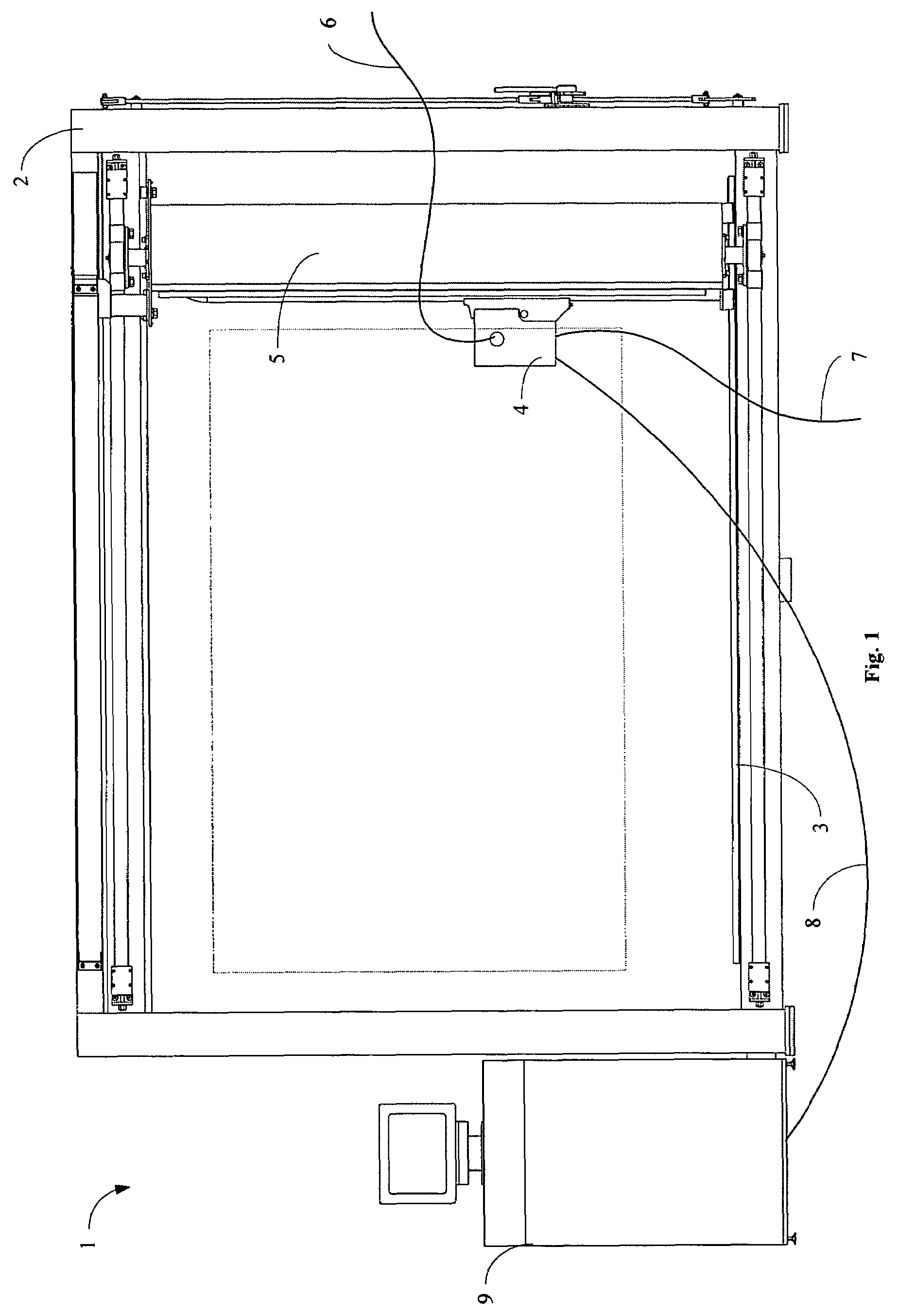
[0056]Referring first to FIG. 1 tufting machine 1 comprises a stand 2 onto which a stretch frame 3 can be mounted. In use, backing fabric is mounted on stretch frame 3. A tufting head 4 is also mounted on the stand in a movement system 5 that is able to translate in X- and Y-directions over the backing fabric. Yarn 6 is provided to the tufting head 4, as well as compressed air 7, electrical power and control signals 8. The control signals 8 are supplied from a computer control system 9 which is operable under the control of a machine readable tufting design pattern comprising a series of vectors and associated control codes.

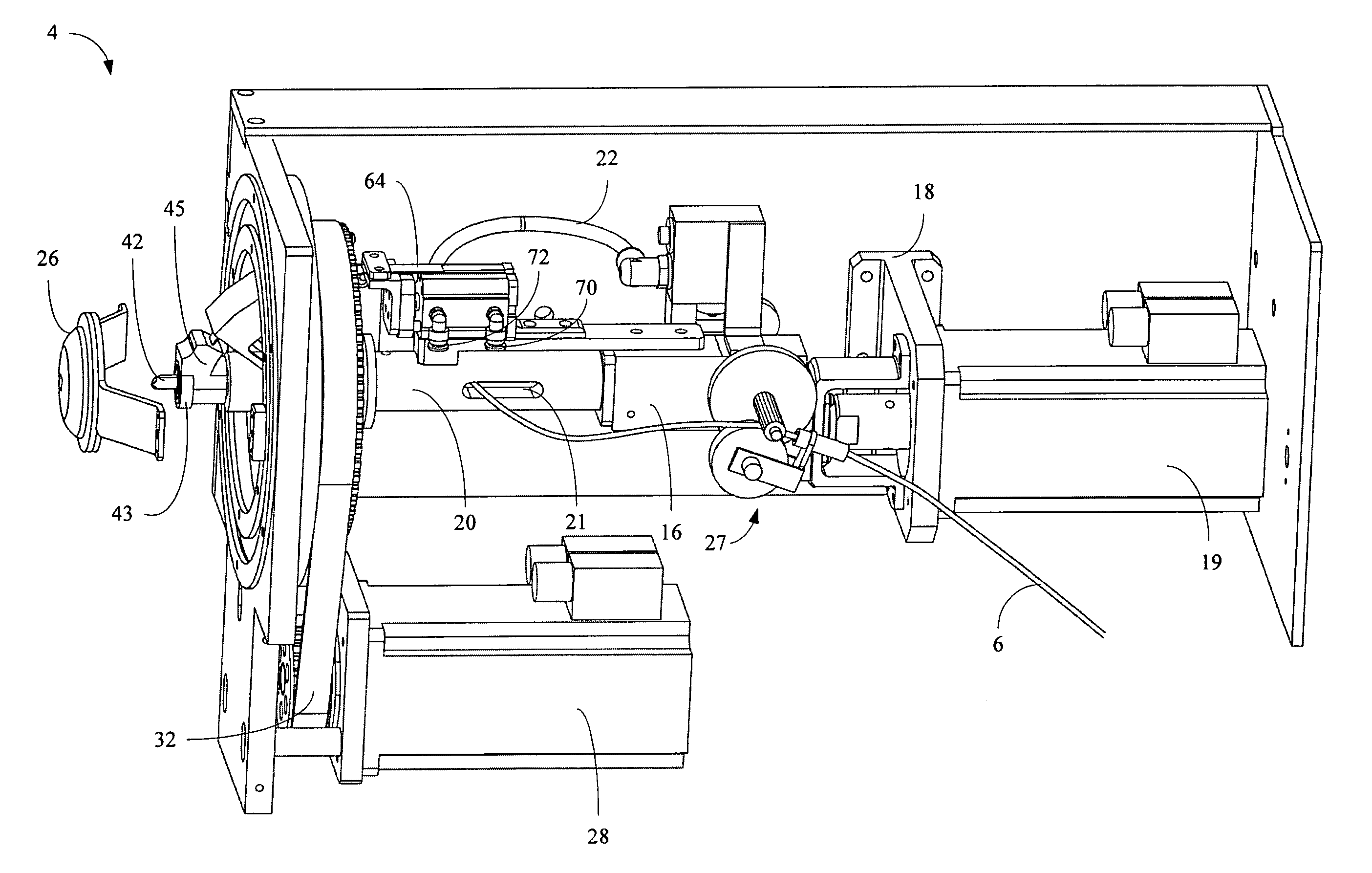
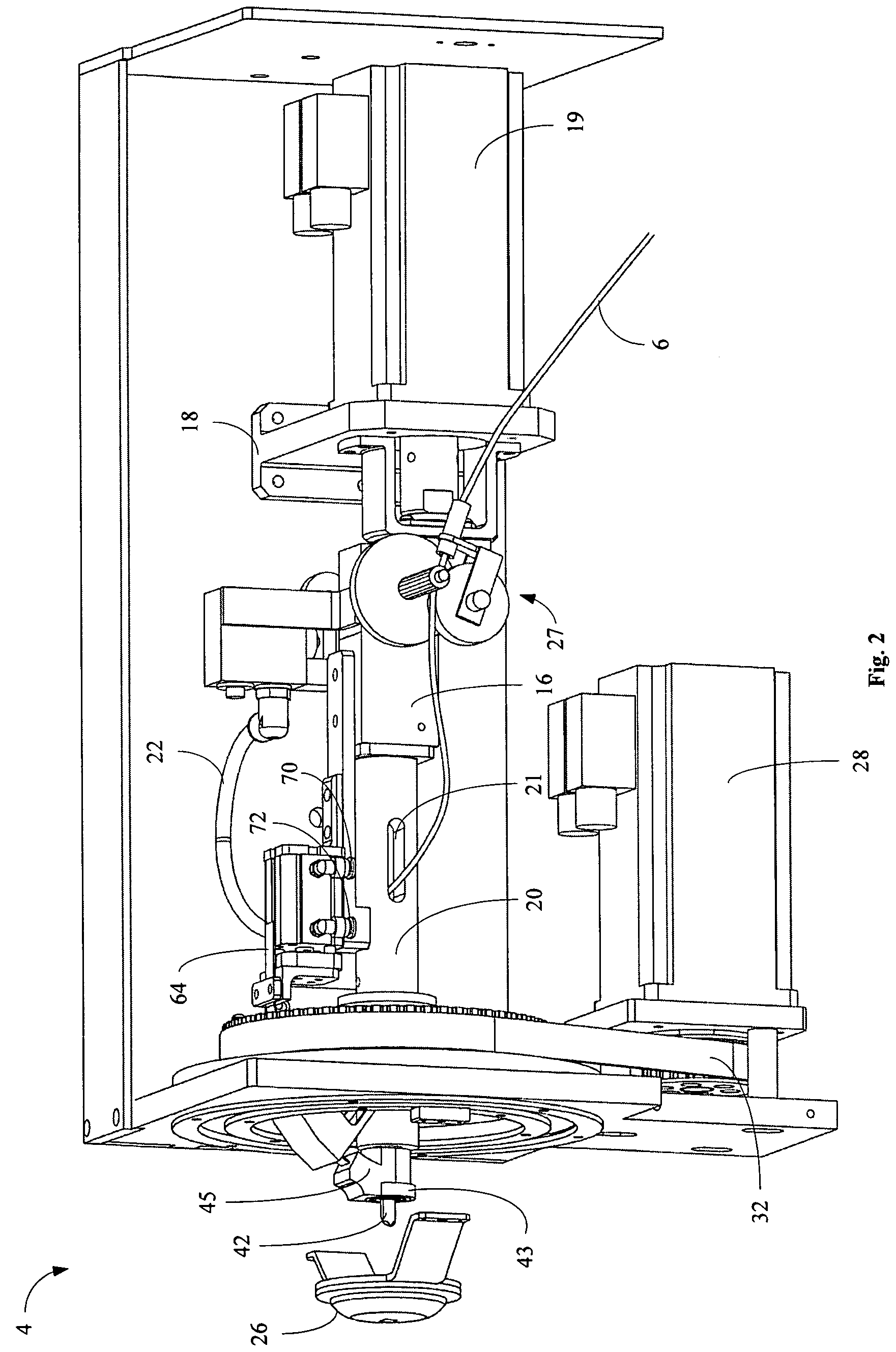
[0057]Referring to FIGS. 2 and 3, the tufting head 4 comprises a frame 12 in which is mounted a tufting mechanism, indicated generally at 14. The mechanism 14 has a gearbox 16 that is mounted to a motor mounting bracket 18 which holds motor 19 in the frame 12. A tufting head barrel 20 extends forwardly from gearbox 16.

[0058]Within barrel 20 is a reciprocating inn...


PUM


Abstract

This invention concerns the production of so called “hand tufted rugs”, carpets and wall hangings by use a “tufting machine” which employs a single hollow needle through which yarn is fed into a backing fabric, to form tufts of yarn. The machine comprises a yarn cutter, in the tufting head, which is selectively operable to cause the tufts to be cut or loop pile. A computer operated motion control system is operable under the control of a machine readable tufting design pattern comprising a series of vectors and associated control codes, to drive the tufting gun as follows: (a) to operate the mechanism and reciprocate the needle to insert tufts into backing fabric. (b) to operate the movement system and move the needle across a two-dimensional plane while inserting tufts, in accordance with the vectors. (c) to lift and lower the foot, in accordance with respective control codes. And, (d) to selectively operate the yarn cutter, in accordance with respective control codes.

Description

TECHNICAL FIELD[0001]This invention concerns the production of so called “hand tufted rugs”, carpets and wall hangings by using a “tufting gun” which employs a single hollow needle through which yarn is fed by high pressure air or by mechanical means, into a backing fabric, to form tufts of yarn. The tufts may be cut pile or loop pile. Such “tufting guns” may be controlled and guided manually by a human operator, or as in this invention, automatically in the context of a computer controlled tufting machine that uses vector based design definition.BACKGROUND ART[0002]“Broad loom tufting machines” typically use a row of several hundred needles to insert row after row of tufts simultaneously into backing fabric which is drawn continuously passed them. Such large scale machines commonly use needles which have an eye to carry the yarn through the backing. It is common practice in broadloom tufting machines to switch between cut pile and loop pile on a stitch by stitch basis, or area by a...

Claims


Application Information

Patent Timeline
Patent Type & Authority Patents(United States)
IPC IPC(8): D05C15/08
CPCD05C15/16D05C15/18
Inventor MILE, JOZWILSON, WILLIAM BRIAN
Owner PERPETUAL MACHINE CO
Why Eureka
Try Eureka