Ethane plus and HHH process for NGL recovery

a technology of ethane and ngl, which is applied in the field of recovery of ethane, propane and ngl from natural gas, can solve the problems of inability to obtain presently commercially required recovery of ethane from ngl feeds, lower outlet temperatures, and inability to achieve maximum heat integration between cold and hot streams not always optimally effected, so as to improve the fractionation effect of the absorber, reduce the buildup of ethane, and improve the effect of th

Inactive Publication Date: 2007-05-22
MOSTAFA HUSSEIN MOHAMED ISMAIL
View PDF11 Cites 187 Cited by
  • Summary
  • Abstract
  • Description
  • Claims
  • Application Information

AI Technical Summary

Benefits of technology

[0043]A second form of the invention comprises a process for propane recovery using a cryogenic absorber and a deethanizer. The equipment list is similar to the first form of the invention, in that a sales gas compressor, expander/compressor and two air coolers are used. A feed gas is partly condensed, with the liquid part being further cooled and fed to a deethanizer and the vapor part being expanded and fed to a lowest stage of a cryogenic absorber. An overhead gas stream from the absorber becomes the product gas stream. A solvent stream for the absorber is formed from the overhead gas stream from the deethanizer after compression via expander shaft compressor, air cooling and flashing to absorber pressure. The evaporative eff...

Problems solved by technology

U.S. Pat. No. 6,581,410 B1.Process configuration and operating conditions whereby maximum heat integration between cold and hot streams are not always optimally effected.
This results in a lower outlet temperatures of cold streams and accordingly a lower overall UA.In propane recovery, relatively large energy consumption in a de-ethanizer bottom reboiler due to operation at pressures higher than a cryogenic absorber.In propane recovery, a de-ethanizer must be designed with a relatively large diameter.In propane recovery mode, extra equipment must be installed to provide chilling of feed gas...

Method used


Image

  • Ethane plus and HHH process for NGL recovery
  • Ethane plus and HHH process for NGL recovery
  • Ethane plus and HHH process for NGL recovery

Examples


case 4

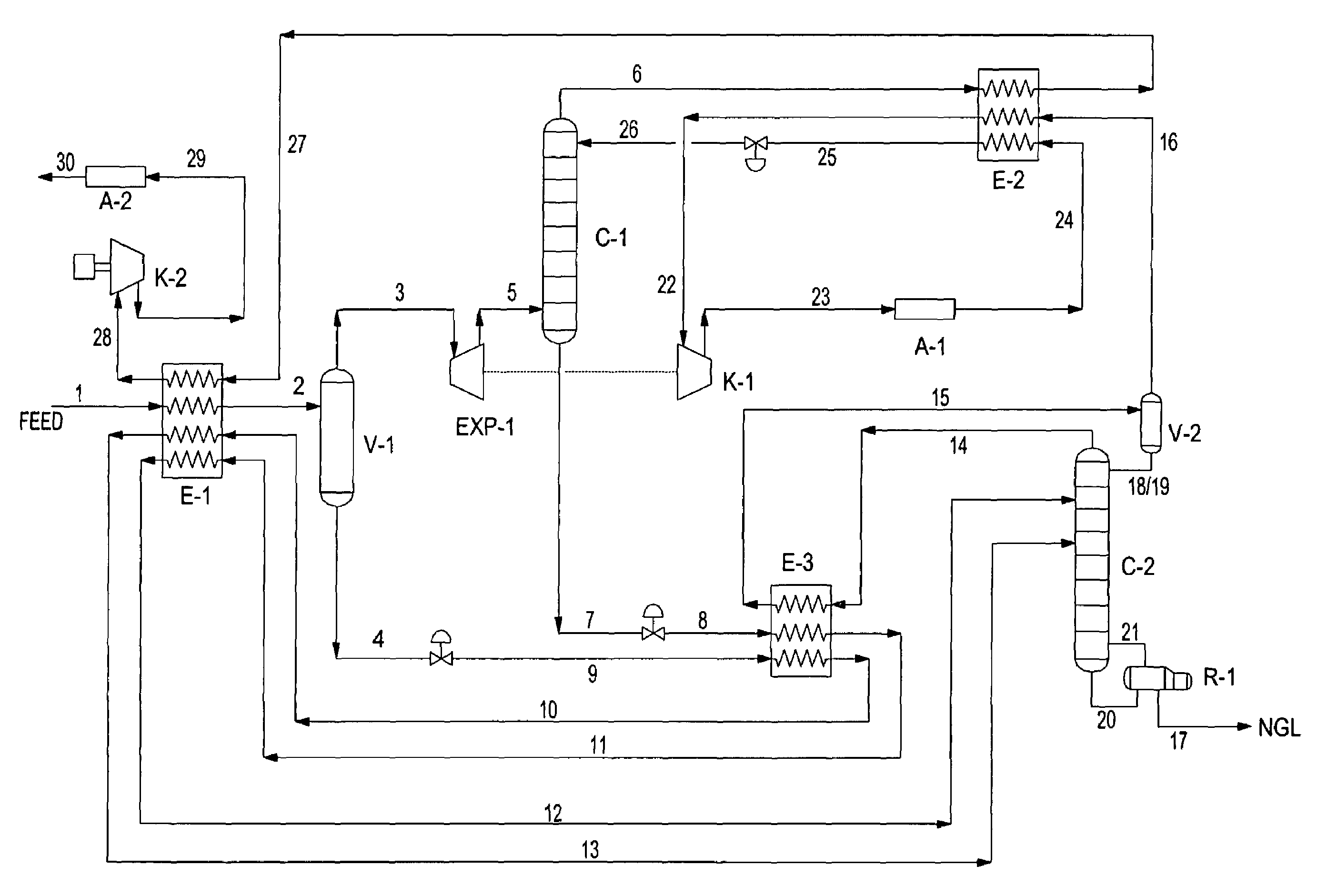
[0061]Case 4 is shown in FIG. 3 and its operating data shown in Table 4. Case 4 is for propane recovery. Feed gas 1 is cooled in exchanger E-1 against streams 27, 10 and 11 to form stream 2, a partly condensed stream separated in vessel V-1 to form a vapor stream 3 and a liquid stream 4. Stream 4 is flashed to form stream 9, which is cooled in exchanger E-3 and exchanger E-1 respectively to form streams 10 and 13. Stream 13 is fed to a mid stage of deethanizer column C-2. Column C-2 produces an overhead vapor stream 14 that is cooled in exchanger E-3 to form stream 15, which is separated into vapor and liquid streams 16 and 18 / 19. Stream 18 / 19 is the entire reflux for column C-2. A bottom liquid stream 20 of column C-2 is split to form reboiling stream 21 and NGL product stream 17.

[0062]In FIG. 3, vapor stream 16 is heated in exchanger E-2, compressed in compressor K-1, cooled in exchanger A-1, cooled in exchanger E-2, and flashed across a valve to respectively form streams 22, 23, ...


PUM


Abstract

The present invention relates to methods for separating and recovering ethane, propane and heavier components from a feed gas, e.g. raw natural gas or a refinery or petroleum plant gas stream or a petrochemical plant gas stream. These methods employ a common new concept which is the use of the turbo-expander shaft compressor to generate the reflux requirement for the cryogenic absorber or distillation columns. The power of the turbo-expander which is absorbed by the shaft compressor is always high enough so that reflux generation by a specific gas compression through the expander shaft compressor and subsequent cooling, condensation and sub-cooling can always be easily maintained. The present invention allows for higher cryogenic absorber pressure and a lower demethanizer/de-ethanizer column pressure thus eliminating the common cryogenic pump at absorber bottom. The present invention ultimately results in a lower residue compression and utilities consumption. The present invention as such allows for a higher 99+% recovery of NGL from the feed gas stream.

Description

[0001]This application claims benefit of U.S. provisional application Ser. No. 60 / 500,014 filed Sep. 5, 2003.BACKGROUND OF THE INVENTION[0002]The present invention relates to processes for recovery of ethane, propane and NGL from natural gas whereby the expander shaft compressor is located in a new locations permitting the reflux generation requirement for the cryogenic absorber and / or gas processing distillation columns.[0003]Current prior art processes for recovery of natural gas liquids comprise:[0004]A large sales gas export compressor that unnecessarily increases utilities, the large size needed to compensate for a high pressure drop across a turbo expander that provides some process refrigeration and dictating a low cryogenic absorber pressure.[0005]A relatively high capacity cryogenic pump to pump a bottoms liquid stream from a cryogenic absorber.[0006]Expander feed gas being at least partly condensed and used as a reflux to a demethanizer, causing loss of propane from a bott...

Claims


Application Information

Patent Timeline
IPC IPC(8): F25J3/00
CPCF25J3/0209F25J3/0233F25J3/0238F25J3/0242F25J2200/02F25J2200/04F25J2200/50F25J2200/70F25J2200/74F25J2200/76F25J2200/78F25J2205/04F25J2210/06F25J2230/08F25J2230/20F25J2230/60F25J2235/60F25J2240/02
Inventor MOSTAFA, HUSSEIN MOHAMED ISMAIL
Owner MOSTAFA HUSSEIN MOHAMED ISMAIL
Why Eureka
Try Eureka