Variable ratio pedal assembly

a technology of variable ratio and pedal assembly, which is applied in the direction of mechanical control devices, braking systems, controlling members, etc., can solve the problems of shortening the travel of the master cylinder push rod, hurting the pedal feel, and the push rod not being fully stroked to “bottom out” the master cylinder, etc., to achieve the effect of decreasing the ratio and increasing the ratio

Active Publication Date: 2007-05-22
VENTRA GRP
View PDF24 Cites 26 Cited by
  • Summary
  • Abstract
  • Description
  • Claims
  • Application Information

AI Technical Summary

Benefits of technology

[0014]With this construction, the actuating assembly of this aspect of the invention provides an increased ratio at the beginning of the arm motion and a decreased ratio towards the end of the arm motion. When this aspect of the invention is implemented as a variable ratio brake pedal assembly this feature advantageously allows for an early peak in the pedal's force ratio desirable for situations such as booster assist failure situations, but only briefly so that overall pedal travel and “pedal feel” is more like a lower ratio pedal assembly. Also, when the pedal assembly is used for operating the vehicle brakes, an advantage of providing an early peak in pedal ratio is that this is when the operator's leg is in the best position to push down on the pedal in booster assist failure situations, and coinciding the early peak with this position provides for optimal leverage.

Problems solved by technology

However, the higher pedal ratio results in a shorter travel of the master cylinder push rod.
However, as noted above, increasing the pedal ratio to accommodate the FMVSS requirements can hurt “pedal feel,” which is the operator's perception of comfort or reasonable operation.
The shorter travel of the master cylinder push rod may result in the push rod not being fully stroked to “bottom out” the master cylinder.
However, these variable ratio brake pedal assemblies include complex linkage mechanisms.

Method used


Image

  • Variable ratio pedal assembly
  • Variable ratio pedal assembly
  • Variable ratio pedal assembly

Examples


Embodiment Construction

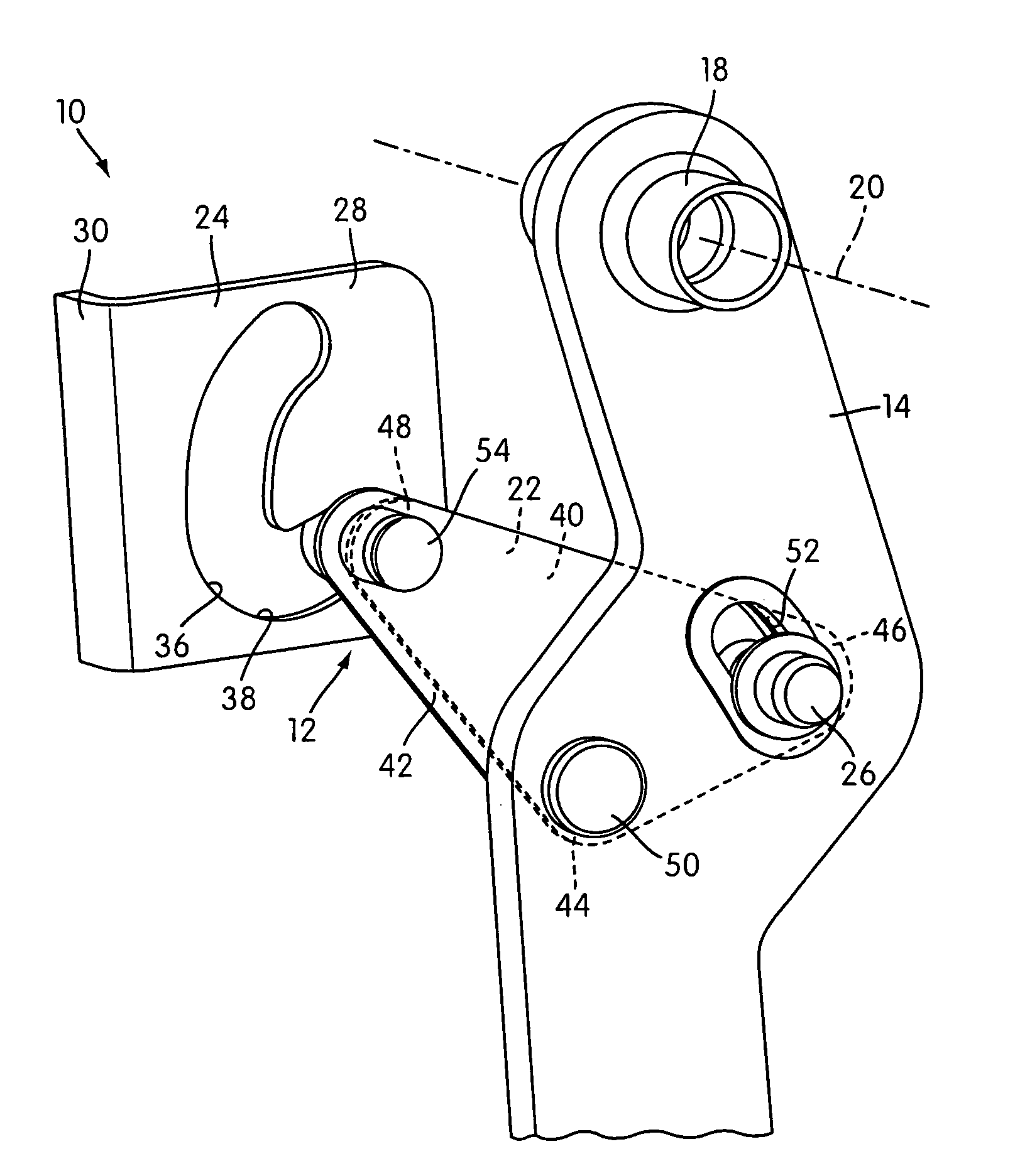
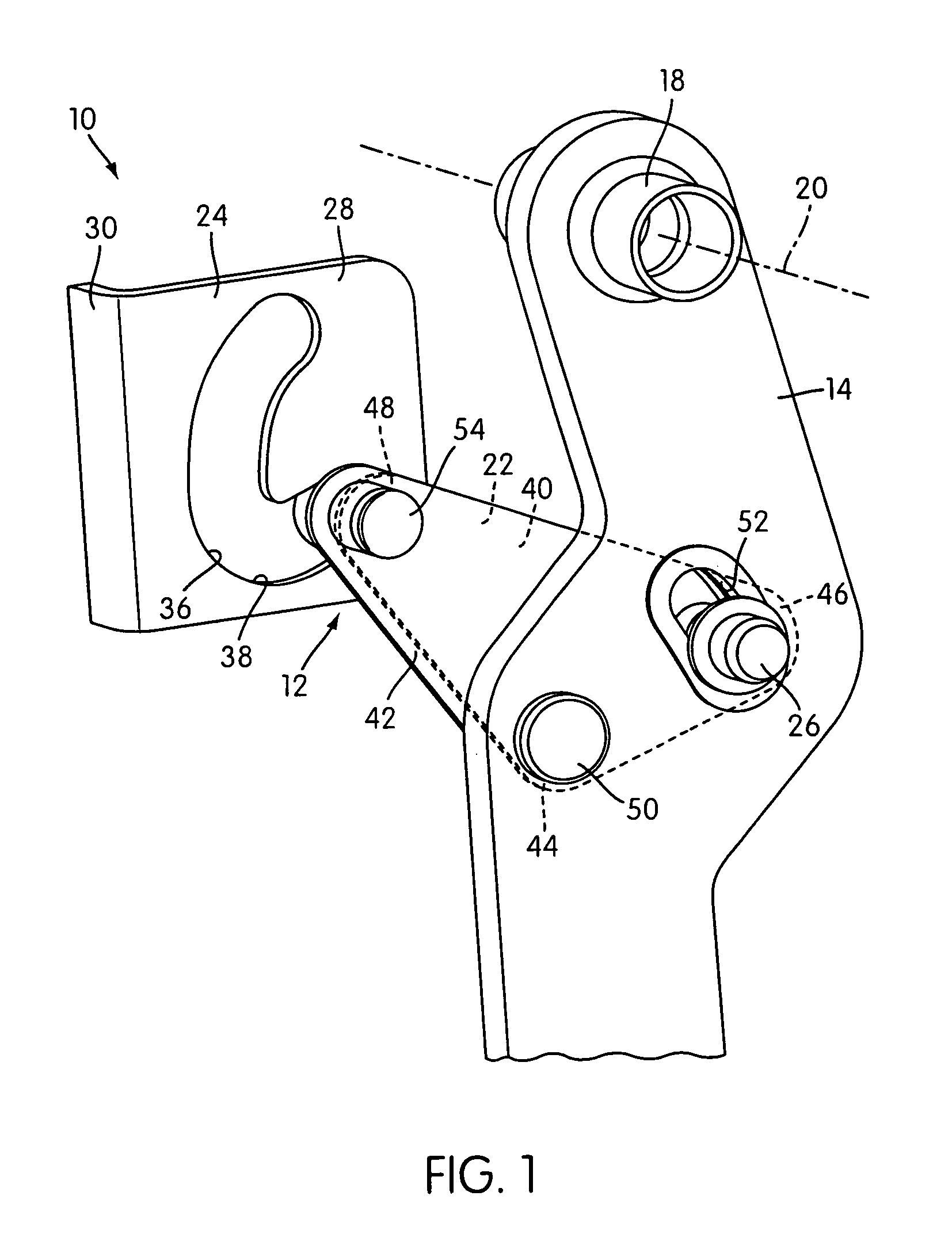
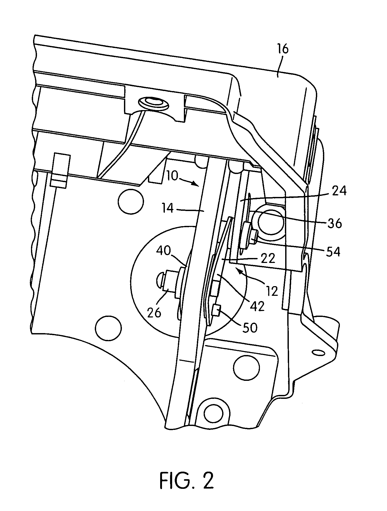
[0039]FIGS. 1 and 2 illustrate a variable ratio actuating assembly 10 including a cam guided booster pin linkage assembly 12 constructed according to an embodiment of the present invention. In the illustrated embodiment, the actuating assembly 10 is in the form of a pedal assembly, and particularly a brake pedal assembly for a vehicle. The brake pedal assembly 10 may be of the adjustable-type or the conventional non-adjustable type. However, the assembly 10 may be a hand-operated parking brake assembly, a parking brake pedal assembly, or any other lever assembly having a lever for which a variable pedal ratio is desired.

[0040]Moreover, as an optional feature, the cam guided booster pin linkage assembly 12 may be retrofit to an existing pedal assembly having a substantially constant pedal ratio in order to convert the pedal assembly into a variable ratio pedal assembly having a variable pedal ratio. Thus, the cam guided booster pin linkage assembly 12 may be utilized with any type of...


PUM


Abstract

The present invention provides a variable ratio brake pedal actuating assembly with an early increase of geometric ratio or force ratio and a subsequent decrease. The actuating assembly comprises a mount, an arm, an input portion and an input connector. The input connector is operatively connected to the arm such that the ratio varies as the arm moves. The ratio reaches a maximum peak prior to moving 30% of the fully stroked position. Also provided is an actuating assembly that uses a cam guide structure with a contoured cam surface and a link member. A configuration of the contoured cam surface, a guide slot, and the link member are such that the ratio varies as the arm is moved. Yet another aspect of the present invention is to provide a cam guided booster pin linkage assembly that provides a variable pedal ratio.

Description

[0001]The present application claims priority to U.S. Provisional Application Ser. No. 60 / 524,908, filed Nov. 26, 2003, the entirety of which is hereby incorporated into the present application by reference.BACKGROUND OF THE INVENTION[0002]1. Field of the Invention[0003]The present invention relates to variable ratio actuating assemblies for vehicles, such as brake pedal assemblies having a variable pedal ratio. Also, the present invention may relate to other types of levers wherein variable ratio is used.[0004]2. Description of Related Art[0005]Actuating assemblies for operating input elements of vehicles are well-known and include assemblies such as brake pedal assemblies and hand lever assemblies. For example, known brake pedal assemblies include a pedal arm having one end that is pivotally mounted to a mounting structure (e.g., a bracket) provided in the vehicle to enable pivotal movement of the pedal arm about an operating pivot axis. The pedal arm includes an input connector i...

Claims


Application Information

Patent Timeline
Patent Type & Authority Patents(United States)
IPC IPC(8): G05G1/04B60T7/06B60T11/08F15B13/02
CPCB60T7/06B60T11/08Y10T74/2057Y10T74/20528
Inventor LEONARD, JUBE R.SYKES, MICHAEL R.PORCO, DOMINIC D.
Owner VENTRA GRP
Why Eureka
Try Eureka