Plasma reactor with overhead RF source power electrode with low loss, low arcing tendency and low contamination

a technology of source power electrode and rf source, which is applied in the direction of arc welding apparatus, plasma technique, chemical vapor deposition coating, etc., can solve the problems of changing the characteristics of the ceiling electrode, unable or extraordinarily expensive to reproduce the same behavior in different reactors of identical design, and unable to control the delivered source power within the requisite tolerances

Inactive Publication Date: 2007-05-22
APPLIED MATERIALS INC
View PDF129 Cites 73 Cited by
  • Summary
  • Abstract
  • Description
  • Claims
  • Application Information

AI Technical Summary

Problems solved by technology

Precise control of the power delivered to the plasma is required now more than ever because of shrinking microelectronic device geometries which reduce the tolerance in etch rate and therefore plasma density and source power.
Several problems can cause the ceiling electrode to perturb the RF source power delivered to the plasma, thereby making it impossible to control the delivered source power within the requisite tolerances.
One problem is the tendency of the plasma to corrode or etch the interior surface of the ceiling electrode, thereby changing the characteristics of the ceiling electrode.
Another problem is the tendency of process gases inside gas delivery passages within the ceiling electrode to arc, thereby absorbing RF power that would otherwise have been delivered to the plasma.
But this introduces a new problem tending to affect the power delivered to the plasma: the semiconductor layer tends to absorb some of the RF power applied to the ceiling electrode, and the amount absorbed varies greatly with small variations in the characteristics of the semiconductor layer, such as thickness, impurity concentration, temperature, etc.
This makes it impossible or extraordinarily expensive to reproduce identical behavior in different reactors of identical design.
It also makes it difficult to control the power delivered to the plasma because of unavoidable variations in ceiling temp

Method used


Image

  • Plasma reactor with overhead RF source power electrode with low loss, low arcing tendency and low contamination
  • Plasma reactor with overhead RF source power electrode with low loss, low arcing tendency and low contamination
  • Plasma reactor with overhead RF source power electrode with low loss, low arcing tendency and low contamination

Examples


Embodiment Construction

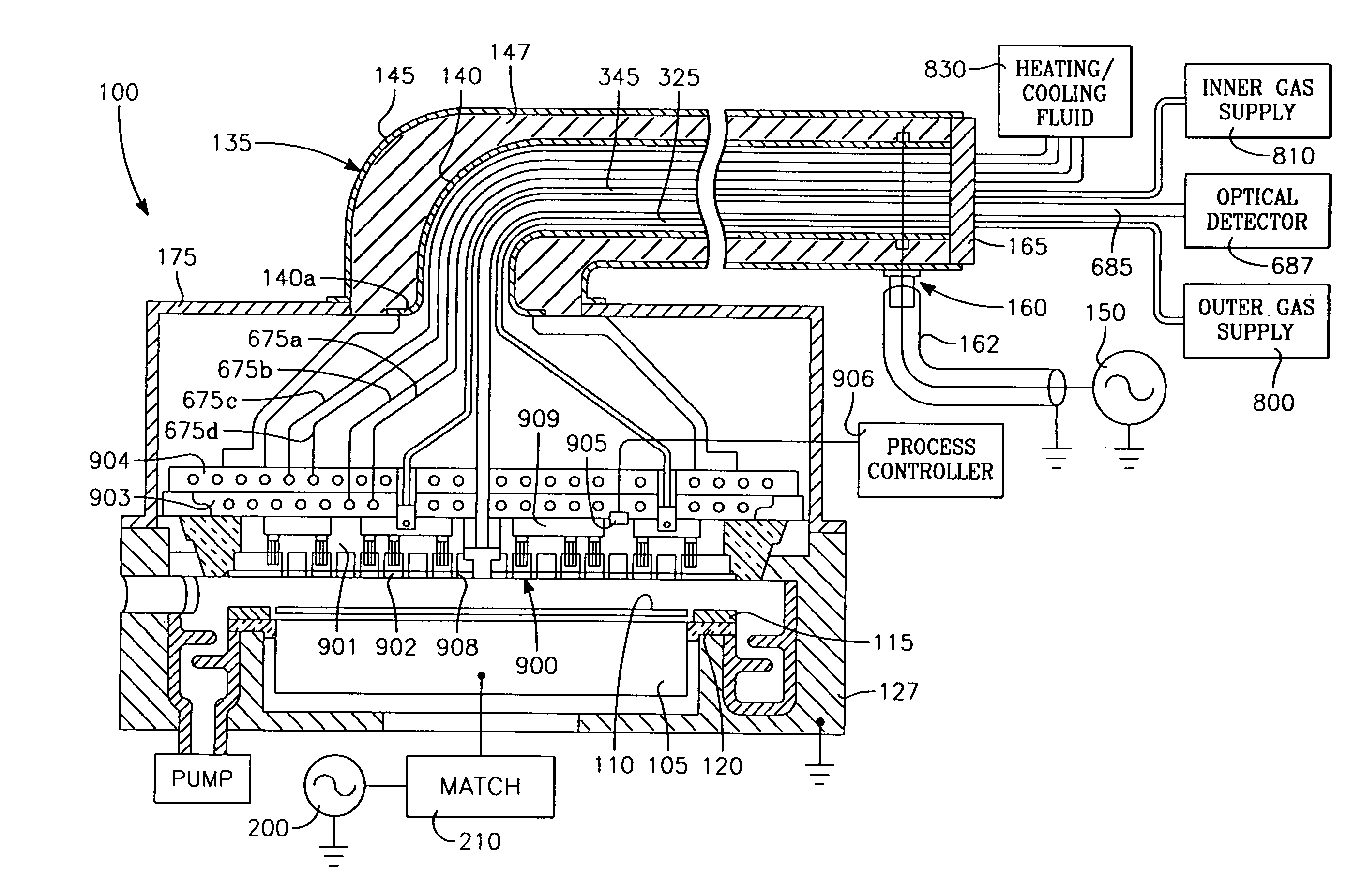
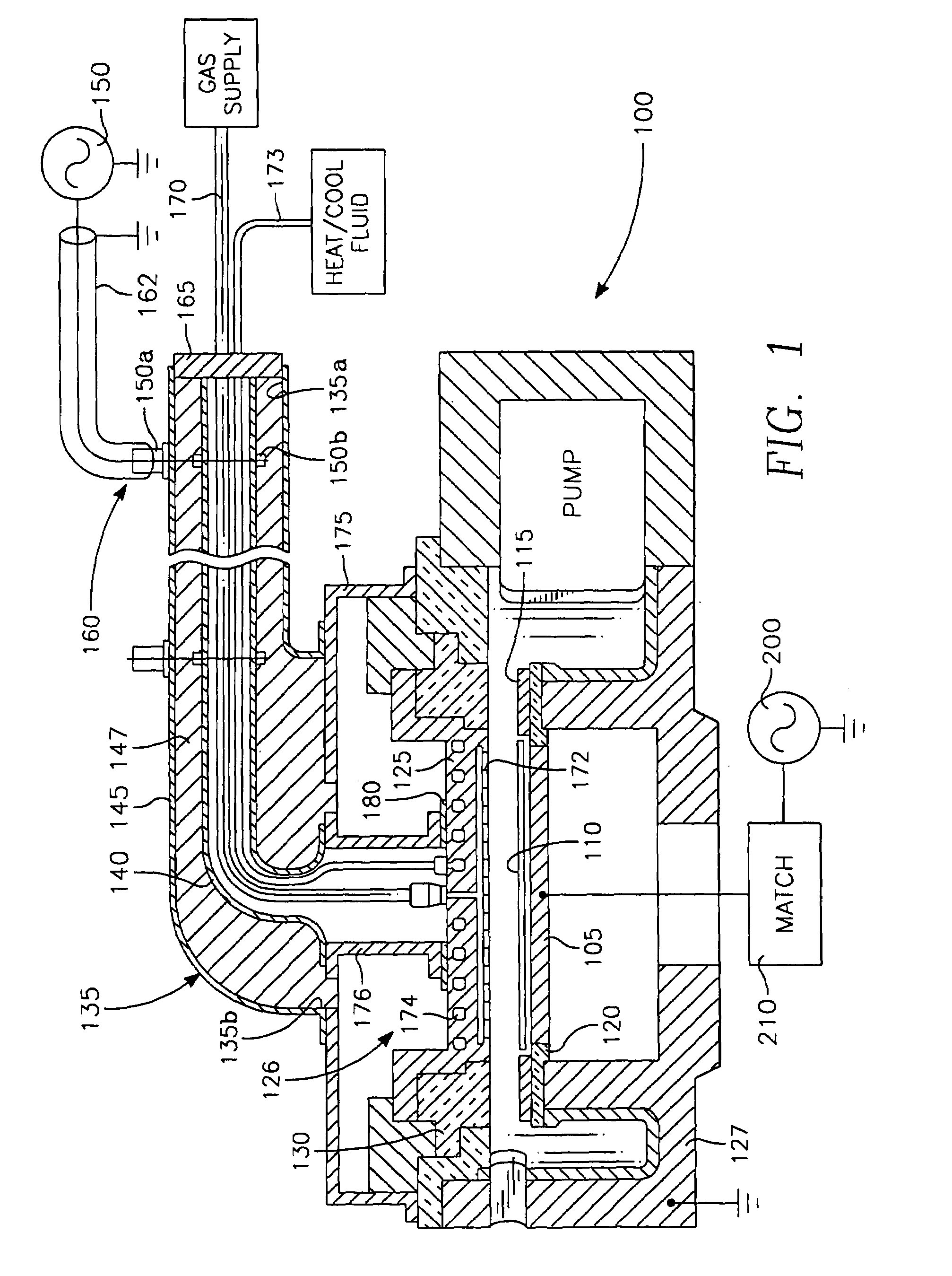
[0040]Referring to FIG. 1, a plasma reactor includes a reactor chamber 100 with a wafer support 105 at the bottom of the chamber supporting a semiconductor wafer 110. A semiconductor ring 115 surrounds the wafer 110. The semiconductor ring 115 is supported on the grounded chamber body 127 by a dielectric (quartz) ring 120. In one embodiment, this is of a thickness of 10 mm and dielectric constant of 4. The chamber 100 is bounded at the top by a disc shaped overhead aluminum electrode supported at a predetermined gap length above the wafer 110 on grounded chamber body 127 by a dielectric (quartz) seal. The overhead electrode 125 also may be a metal (e.g., aluminum) which may be covered with a semi-metal material (e.g., Si or SiC) on its interior surface, or it may be itself a semi-metal material. An RF generator 150 applies RF power to the electrode 125. RF power from the generator 150 is coupled through a coaxial cable 162 matched to the generator 150 and into a coaxial stub 135 con...


PUM

PropertyMeasurementUnit
Fractionaaaaaaaaaa
Diameteraaaaaaaaaa
Diameteraaaaaaaaaa

Abstract

A gas distribution ceiling electrode for use as a capacitive source power applicator and gas distribution showerhead in a plasma reactor includes a metal base and a process-compatible protective layer on the interior surface of he electrode having a dopant impurity concentration within a range corresponding to a minimal change in RF power absorption in the protective layer at an RF source power frequency with changes in coating temperature and or thickness. The metal base may have a set of first arcuately slotted gas passages and a set of pressure-dropping orifices coinciding axially with the top ends of the gas passages. The protective coating a set of arcuately slotted gas passages in registration gas passages of the metal base. The pressure drop in the orifices and the electric field drop in the slotted gas passages are both sufficient to maintain the pressure and electric field within the gas passages within a range that prevents arcing.

Description

CROSS-REFERENCE TO RELATED APPLICATIONS[0001]This application is a continuation-in-part of U.S. application Ser. No. 10 / 028,922 filed Dec. 19, 2001 by Daniel Hoffman et al., and assigned to the assignee of the present application, which is a continuation-in-part of U.S. application Ser. No. 09 / 527,342 filed Mar. 17, 2000 by Daniel Hoffman et al., now U.S. Pat. No. 6,528,751, assigned to the assignee of the present application.BACKGROUND OF THE INVENTION[0002]Plasma processing of semiconductor wafers in the manufacture of microelectronic integrated circuits is used in dielectric etching, metal etching, chemical vapor deposition and other processes. Such plasma processes require precise control of process parameters, such as the amount of plasma power delivered to the plasma, for example. This parameter is affected by a number of variables, including the ability of the impedance matching device between the plasma source power generator and the reactor's RF power applicator to provide ...

Claims


Application Information

Patent Timeline
IPC IPC(8): B23K10/00H01J37/32H01L21/205H05H1/46H01L21/3065
CPCH01J37/32082H01J37/32183
Inventor HOFMAN, DANIEL J.SUN, JENNIFER Y.THACH, SENHYE, YAN
Owner APPLIED MATERIALS INC
Why Eureka
Try Eureka