Converter with start-up circuit
a start-up circuit and converter technology, applied in the field of converters, can solve the problems of unsolved problems mentioned below, large energy loss, and large energy loss of conventional dc-dc converters, and achieve the effect of increasing the cost and size of the converter and large energy loss
- Summary
- Abstract
- Description
- Claims
- Application Information
AI Technical Summary
Benefits of technology
Problems solved by technology
Method used
Image
Examples
first embodiment
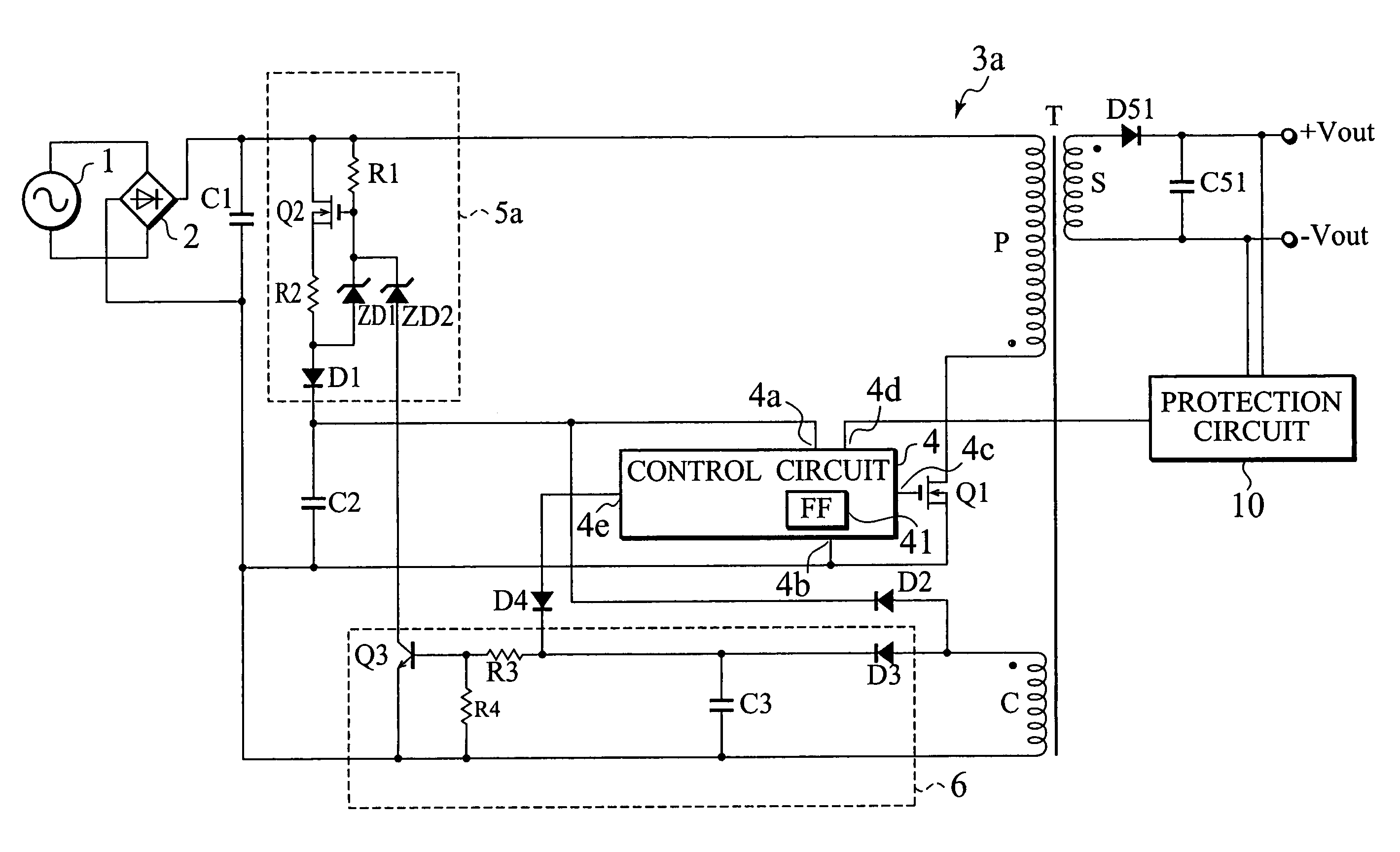
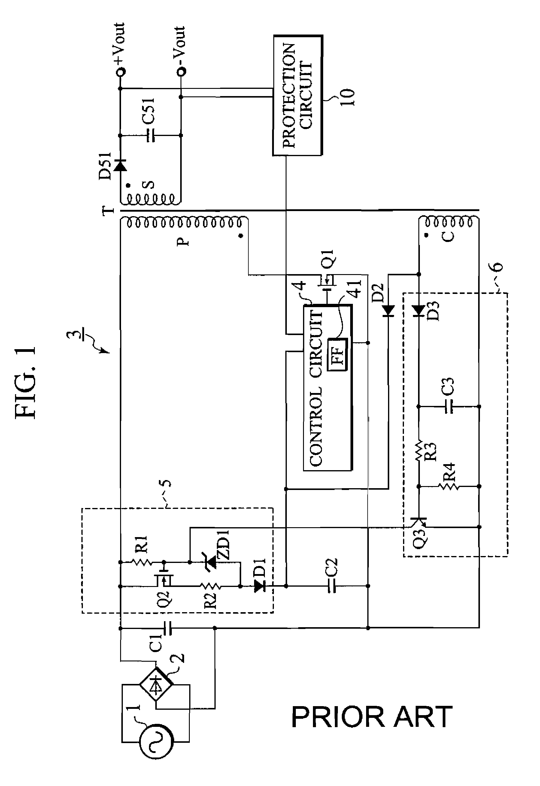
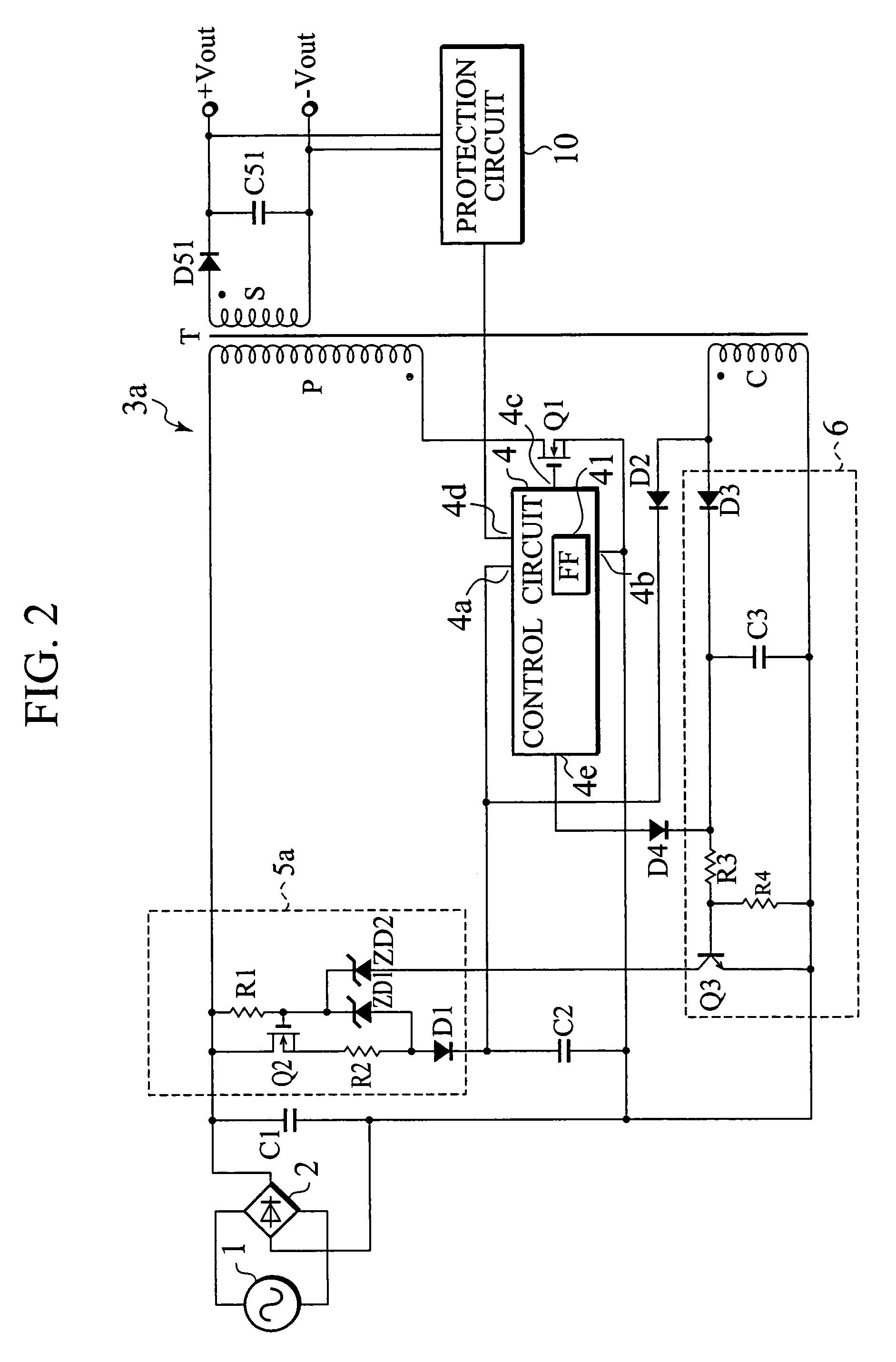
[0036]FIG. 2 is a view showing an arrangement of a DC-DC converter according to the first embodiment of the present invention. The DC-DC converter of FIG. 2 is different from the conventional DC-DC converter of FIG. 1 in that it additionally has a Zener diode ZD2 and a diode D4. In the DC-DC converter of FIG. 2, the same parts as those of the conventional converter of FIG. 1 are represented with the same reference marks.
[0037]In FIG. 2, a sinusoidal wave voltage from an AC power source 1 is rectified and smoothed by a full-wave rectifying circuit 2 and a capacitor C1, to provide a DC voltage. The DC voltage is supplied to the DC-DC converter 3a, which converts the input DC voltage into another DC voltage that is output from output terminals +Vout and −Vout.
[0038]The arrangement of the DC-DC converter 3a will be explained in detail. The capacitor C1 is connected through a primary winding P of a transformer T to a switching element Q1 made of a MOSFET. The switching element Q1 is turn...
second embodiment
[0059]FIG. 4 is a view showing an arrangement of a converter according to the second embodiment of the present invention consisting of a power-factor improving converter and a DC-DC converter. In the converter of the second embodiment, the power-factor converter 7 has a choke coil L1, a switching element Q4, a diode D7, a power-factor improving control circuit (PFC control circuit) 71, and a capacitor C1 and is arranged in front of the DC-DC converter 3a.
[0060]The DC-DC converter 3a has already been explained in the first embodiment of FIG. 2, and therefore, will not be explained here. Only the power-factor improving converter 7 will be explained. The details of the arrangement of the power-factor improving converter 7 will be explained later.
[0061]In FIG. 4, the choke coil L1, switching element Q4, diode D7, power-factor improving control circuit (PFC control circuit) 71, and capacitor C1 form a step-up chopper circuit. The step-up chopper circuit steps up an input voltage from a ...
third embodiment
[0064]FIG. 5 is a view showing a DC-DC converter according to the third embodiment of the present invention. In the DC-DC converter of the first embodiment, a bias voltage to the gate of the switching element Q2 of the start-up circuit 5a is supplied from the capacitor C1. Unlike this, in the DC-DC converter of the third embodiment, a bias voltage to a gate of a switching element Q2 of a start-up circuit 5b is supplied from an AC power source 1 through diodes D5 and D6 and a resistor R1.
[0065]In the start-up circuit 5b, a first end of the AC power source 1 is connected to an anode of the diode D5. A cathode of the diode D5 is connected through the resistor R1 to the gate of the switching element Q2. A second end of the AC power source 1 is connected to an anode of the diode D6. A cathode of the diode D6 is connected through the resistor R1 to the gate of the switching element Q2. The other parts of the DC-DC converter of FIG. 5 are the same as those of the DC-DC converter of FIG. 2,...
PUM
 Abstract
Description
Claims
Application Information
 - R&D
- Intellectual Property
- Life Sciences
- Materials
- Tech Scout
- Unparalleled Data Quality
- Higher Quality Content
- 60% Fewer Hallucinations
Browse by: Latest US Patents, China's latest patents, Technical Efficacy Thesaurus, Application Domain, Technology Topic, Popular Technical Reports.
© 2025 PatSnap. All rights reserved.Legal|Privacy policy|Modern Slavery Act Transparency Statement|Sitemap|About US| Contact US: help@patsnap.com


