Multi-function heat exchanger

a heat exchanger and multi-functional technology, applied in the field of multi-functional heat exchangers, can solve the problems of high cost of compressed air, difficult to overcome, and unpumpable solid materials, and achieve the effect of preventing thermal energy and reducing the volume of hybrid plastisol

Active Publication Date: 2007-05-22
HB FULLER CO
View PDF2 Cites 17 Cited by
  • Summary
  • Abstract
  • Description
  • Claims
  • Application Information

AI Technical Summary

Benefits of technology

[0013]Another objective of this invention is to provide a means to minimize the volume of the hybrid plastisol held resident in the heater at the temperature at which the material is a solid so that it could still be pumped by plug flow.

Problems solved by technology

Unfortunately, before the hybrid plastisol reaches its melting point, it must pass through a temperature range between 150° F. and 270° F. during which it is a solid.
There are difficult challenges to overcome in order to elevate the temperature of this material from its liquid state at room temperature to its molten state at approximately 280° F. and above.
One specific problem to overcome is that between its room temperature liquid state and molten state at +300° F., the material is an un-pumpable solid.
One major disadvantage to the above is the requirement for compressed air which is a very expensive utility that would have to be supplied to multiple heat exchangers in a manufacturing environment.
A further disadvantage is if plant air availability is interrupted for any reason heat will migrate from the ⅛ inch supply nipple into the supply hose causing material to solidify in the pipe and hose in sufficient volume that it cannot be moved by hydraulic pressure; therefore, material supply is stopped.

Method used


Image

  • Multi-function heat exchanger
  • Multi-function heat exchanger
  • Multi-function heat exchanger

Examples


Embodiment Construction

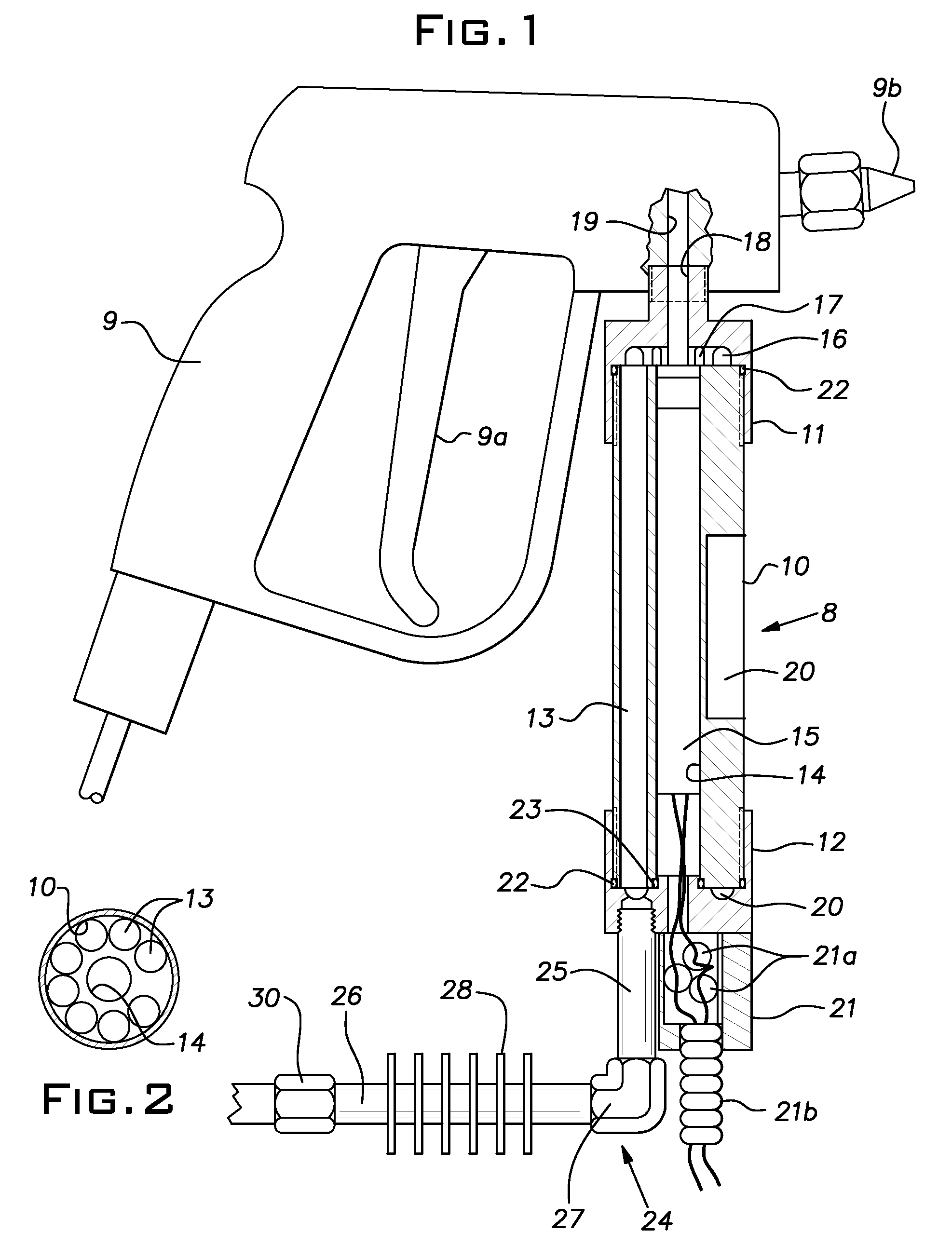
[0024]Referring now to the drawings and in particular to FIG. 1, the entire heat exchanger assembly is indicated by the numeral 8 which is attached to a commercially available manual dispensing gun 9 for dispensing hot melt material. The gun 9 has a trigger 9a and a dispensing nozzle 9b. Since the gun is a commercially available gun a further description of its interior working parts should not be necessary.

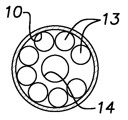
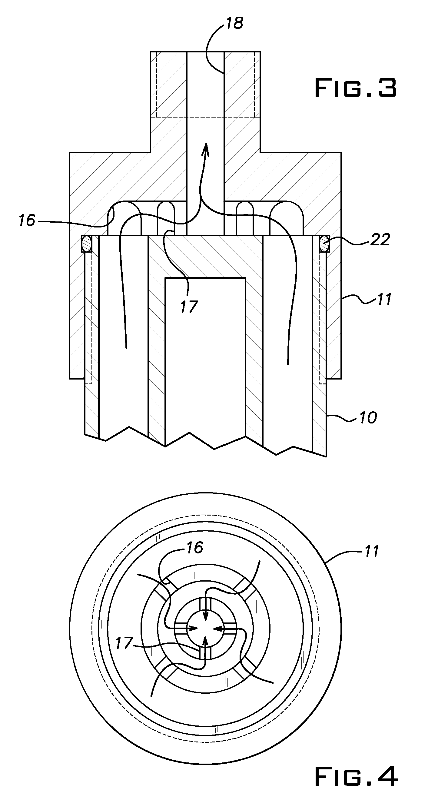
[0025]The heat exchanger assembly 8 has an elongated tubular aluminum body 10 which has a front end cap 11 and a rear end cap 12. As shown in FIGS. 1 and 2, the body 10 has eight symmetrically space fluid ports 13 and a centrally located hole 14 extending longitudinally through the body 10 and retaining therein a heating cartridge 15. The front end cap 11 is made from a thermally conductive metal such as copper or aluminum so as to conduct heat into the heated dispensing gun 9.

[0026]The front end cap 11 has eight, 90° mixing channels 16 and 17 that statically mix the molten mater...


PUM


Abstract

A multi-function heat exchanger for use with a dispensing gun for dispensing hybrid plastisol hot melt material, the heat exchanger having an elongated tubular high temperature heater assembly having a front end hydraulically connected to an inlet port of a dispensing gun and a rear end connected to a heat dissipating assembly which in turn is connected to the outlet end of a supply hose for providing hybrid plastisol material which is liquid at room temperature and under sufficient hydraulic pressure to move the plastisol material through the heat dissipating assembly and the high temperature heater assembly into the dispensing gun when the gun is operated. The heater assembly has a heat source providing sufficient heat to turn the plastisol into a molten liquid as it passes into the dispensing gun. The heat dissipating assembly prevents heat from the high temperature heater assembly from migrating back into the plastisol supply hose.

Description

RELATED US APPLICATIONS[0001]This is a non-provisional application of provisional application Ser. No. 60 / 632,158 filed Dec. 01, 2004 and now pending.FIELD OF THE INVENTION[0002]This invention relates to a heating apparatus that will heat a hybrid plastisol hot melt that is a flowable liquid at room temperature to a temperature wherein the material becomes molten at approximately 280 degrees F. to 350 degrees F. In addition, the device statically mixes the molten liquid converting it to a hot melt as it exits from the apparatus into commercially available hot melt dispensing heads. Once the molten material is dispensed, it has adhesive properties identical to packaging hot melt.BACKGROUND OF THE INVENTION[0003]U.S. patent application #20040029980 describes a hybrid plastisol hot melt composition that is liquid at room temperature. The hybrid plastisol is comprised of various micron-size resins and chemicals suspended in a liquid carrier. When this liquid is heated and mixed, it beco...

Claims


Application Information

Patent Timeline
Patent Type & Authority Patents(United States)
IPC IPC(8): B05B1/24
CPCF24H1/142
Inventor STUMPHAUZER, WILLIAM C.GROTH, HUGH F.
Owner HB FULLER CO
Why Eureka
Try Eureka