Method and apparatus for measuring battery depletion in implantable medical devices

Active Publication Date: 2007-05-22
PACESETTER INC
View PDF11 Cites 82 Cited by
  • Summary
  • Abstract
  • Description
  • Claims
  • Application Information

AI Technical Summary

Benefits of technology

[0014]The method and apparatus can operate over a wide dynamic range of current drawn from a battery in an implantable medical device because the voltage drop across the switched capacitor element is independent of the average current through it. The method and apparatus can also more accurately determine the battery's state of depletion because the switched capaci

Problems solved by technology

A problem with this approach is some battery chemistries, such as carbon monofloride, have terminal characteristics, including terminal voltage and source impedance, which do not change according to the battery's state of depletion.
Additionally, monitoring changes in the battery's terminal voltage might not be an accurate indicator of the battery's state of depletion because the change in terminal voltage between a new battery and a battery at EOL is relatively small, typically 0.2 V.
A problem with this approach is it operates over a limited dynamic range of current d

Method used


Image

  • Method and apparatus for measuring battery depletion in implantable medical devices
  • Method and apparatus for measuring battery depletion in implantable medical devices
  • Method and apparatus for measuring battery depletion in implantable medical devices

Examples


example implementation

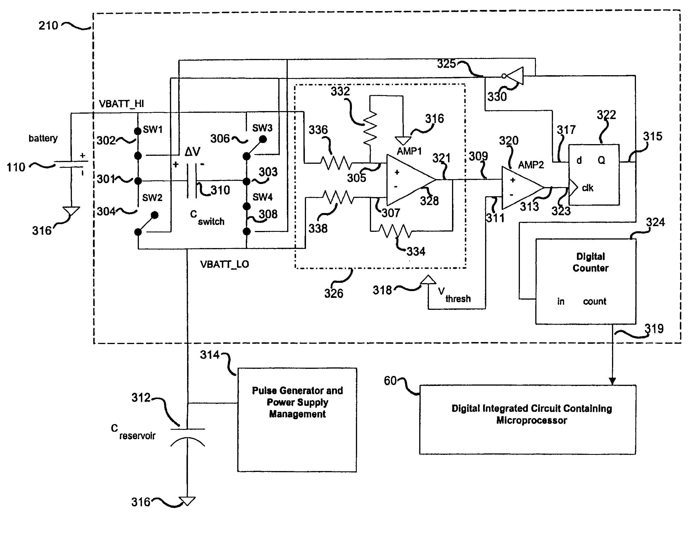
of a Switched Capacitor Current Integrator

[0052]FIGS. 4A–4B illustrate a circuit schematic for an example implementation of switched capacitor current integrator 210, shown in FIG. 3A, in accordance with an example embodiment of the present invention. The embodiment shown in FIGS. 4A–4B operates in the same manner as described above. Selected components of the switched capacitor current integrator of FIGS. 4A–4B are described below in reference to their corresponding elements shown in FIG. 3A.

[0053]FIG. 4A shows four switches Q1–Q4 arranged in an H-bridge configuration with a switched capacitor C2, which corresponds to switched capacitor 310 in FIG. 3A. Switches Q1–Q4 of FIG. 4A are implemented with metal oxide semiconductor field-effect transistors (MOSFETs). Switches Q1 and Q2, which correspond to first and second switches 302 and 304 in FIG. 3A, are coupled together at first node 301 and in series between battery 110 and a reservoir capacitor C3. Reservoir capacitor C3 correspond...


PUM


Abstract

A method and apparatus for measuring battery depletion in an implantable medical device is presented. The apparatus includes first and second switch pairs disposed in series between the battery and a load, and connected in a parallel arrangement with respect to one another. A capacitor is connected in a first polarity between the battery and the load when only first and fourth switches are closed and in a second polarity when only second and third switches are closed. A comparator circuit causes the switches to reverse the capacitor's polarity based on a comparison of the voltage drop across the capacitor to a threshold value. A counter counts the number of times the capacitor reverses polarity, which is proportional to the amount of charge transferred from the battery during its lifetime in the device and indicative of the battery's level of depletion.

Description

BACKGROUND OF THE INVENTION[0001]1. Field of the Invention[0002]The present invention relates generally to battery-powered devices and, more particularly, to measuring battery depletion in battery-powered implantable medical devices.[0003]2. Background Art[0004]Implantable medical devices, such as implantable cardiac devices (ICDs) (e.g., pacemakers, cardioverters, and defibrillators), implantable neurostimulator devices, blood glucose monitoring / delivery devices, etc., are typically battery powered. The state of battery depletion can be monitored or estimated in order to determine the elective replacement (ER) and end-of-life (EOL) points, which enable a physician to schedule appropriate device replacement.[0005]One approach for determining battery depletion is to monitor the battery terminal voltage during the lifetime of the battery in the implantable medical device. Typically the battery terminal voltage decreases as the battery is depleted until a threshold voltage is reached, ...

Claims


Application Information

Patent Timeline
IPC IPC(8): A61N1/00
CPCA61N1/3708A61N1/08
Inventor WEAVER, LYLENEDER, CHARLESWONG, LOUIS
Owner PACESETTER INC
Why Eureka
Try Eureka