Hardware-based HDL code coverage and design analysis

a hardware-based hdl and code technology, applied in the field of electronic systems, can solve the problems of limited capability of software debuggers, limited concurrency of software debuggers, and designers of electronic systems that observe functional failures, and achieve the effect of facilitating correction or adjustment of hdl descriptions

Inactive Publication Date: 2007-05-22
SYNOPSYS INC
View PDF173 Cites 28 Cited by
  • Summary
  • Abstract
  • Description
  • Claims
  • Application Information

AI Technical Summary

Benefits of technology

[0025]Techniques and systems for analysis, diagnosis and debugging fabricated hardware designs at a Hardware Description Language (HDL) level are described. Although the hardware designs (which were designed in HDL) have been fabricated in integrated circuit products with limited...

Problems solved by technology

In the detection step, the designer of the electronic system observes a functional failure.
However, some software debuggers also support limited concurrency such as threaded program execution.
In combination with in-circuit emulators, software debuggers may provide a limited capability to analyze the underlying Central Processing Unit (CPU) of the computer executing the computer software program.
A major disadvantage of software debuggers is, however, that they cannot be used for efficiently debugging general hardware of electronic systems.
Unfortunately, one major disadvantage of functional simulation is the need for simulation models.
For some components such simulation models may not be readily available and must be generated.
Since the ideal testbench must correctly and exhaustively match the behavior of the target environment, creation of a testbench can be very difficult and time consuming.
On the other hand, a testbench that is too simple will not provide the necessary coverage to find all the design errors.
Although functional simulation is useful, using functional simulation to debug design errors is too burdensome.
Not only are the testbenches difficult to create, but also the more complex the HDL design is, the lower the performance of functional simulation.
Accordingly, its low performance makes it impractical to use functional simulation either to debug real-time applications or to concurrently debug hardware and software of complex electronic systems.
One disadvantage of formal verification is that it is impractical to use to re-produce functional failures observed in a running electronic system.
Both techniques, functional simulation and formal verification, have the major disadvantage that they do not operate on fabricated hardware.
Thus, their use is limited to debugging design errors.
As such, neither technique is applicable for debugging manufacturing faults, environment errors, timing errors and/or tool errors.
Also, inadequacies in the testbench have the potential to hide or introduce design errors in the HDL design during functional simulation which can later, when the HDL design is fabricated, show up as functional failures of the running electronic system.
However, since in-circuit emulators only work for the specific target CPU for which they were built, in-circuit emulators are in...

Method used


Image

  • Hardware-based HDL code coverage and design analysis
  • Hardware-based HDL code coverage and design analysis
  • Hardware-based HDL code coverage and design analysis

Examples


Embodiment Construction

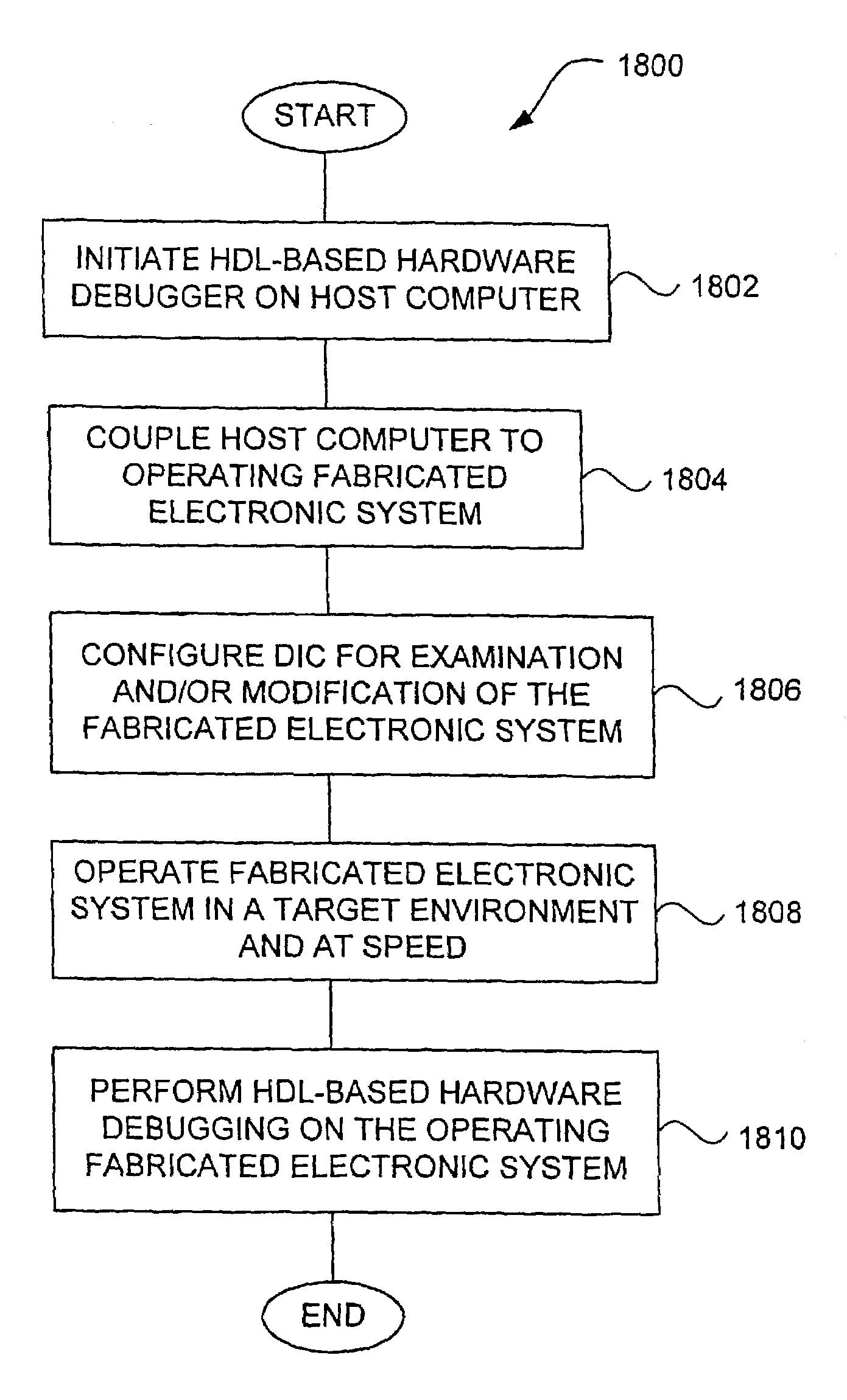
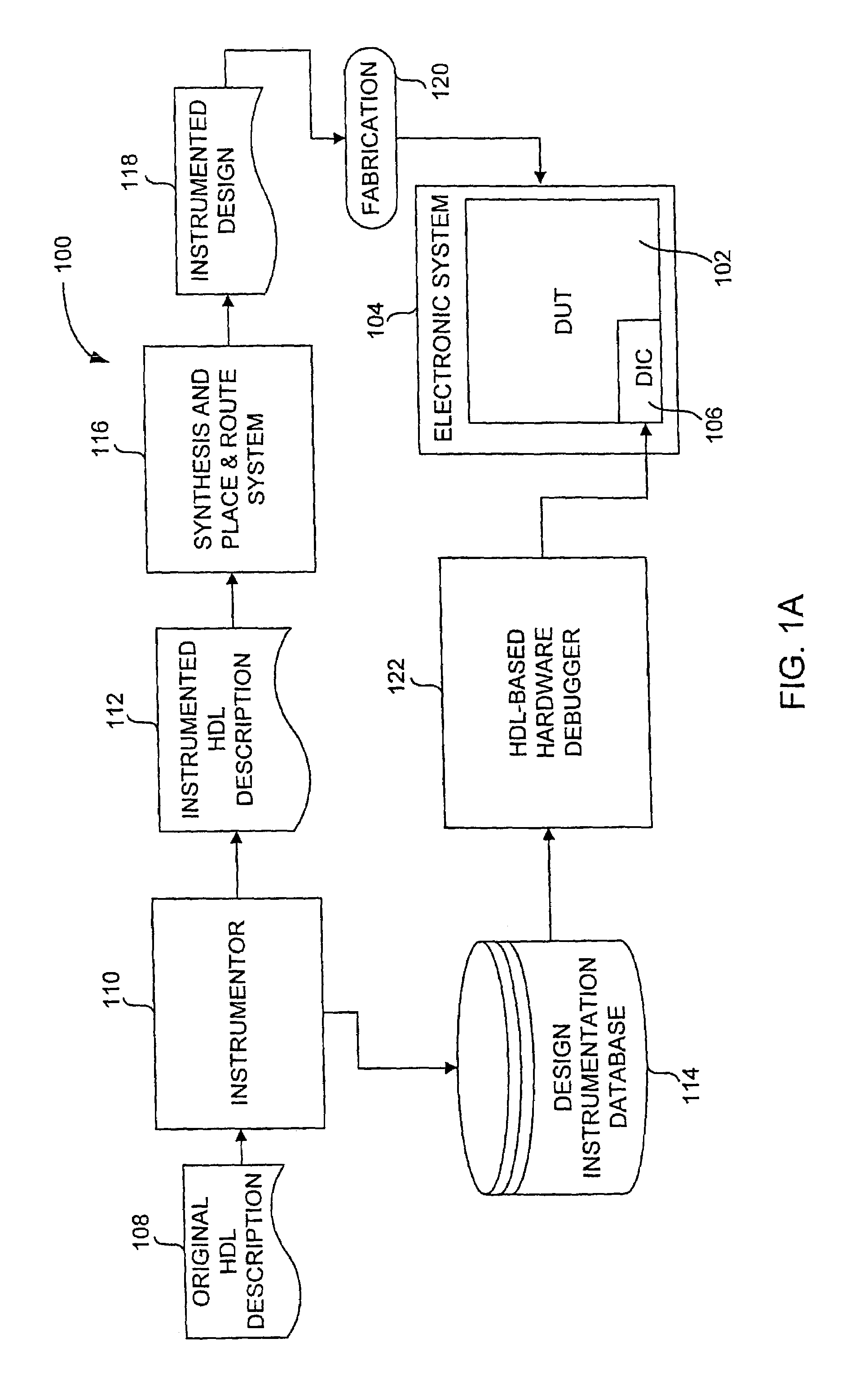
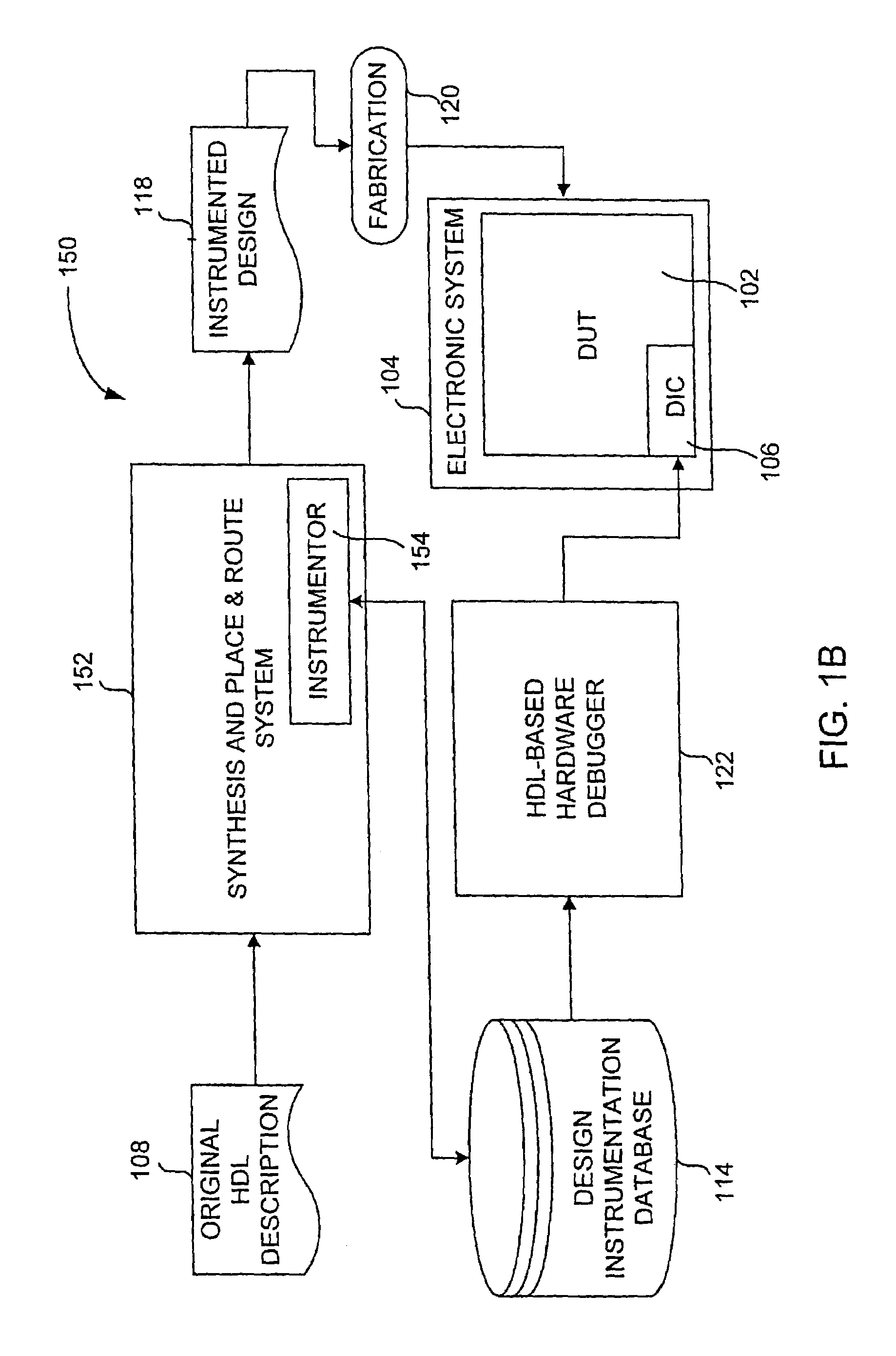
[0060]The present invention relates to techniques and systems for analysis, diagnosis and debugging fabricated hardware designs at a Hardware Description Language (HDL) level. Although the hardware designs (which were designed in HDL) have been fabricated in integrated circuit products with limited input / output pins, the invention enables the hardware designs within the integrated circuit products to be comprehensively analyzed, diagnosed, and debugged at the HDL level at speed. The ability to debug hardware designs at the HDL level facilitates correction or adjustment to the HDL of the hardware designs.

[0061]The following discussions will be made clearer by a brief review of the relevant terminology as it is typically (but not exclusively) used. Accordingly, to assist readers in understanding the terminology used herein, the following definitions are provided. “Software” is defined as but not limited to programming language content written using a programming language. Examples of ...


PUM


Abstract

Techniques and systems for analysis, diagnosis and debugging fabricated hardware designs at a Hardware Description Language (HDL) level are described. Although the hardware designs (which were designed in HDL) have been fabricated in integrated circuit products with limited input/output pins, the techniques and systems enable the hardware designs within the integrated circuit products to be analyzed, diagnosed, and debugged at the HDL level at speed. The ability to debug hardware designs at the HDL level facilitates correction or adjustment of the HDL description of the hardware designs. Moreover, various embodiments related to HDL code coverage are described.

Description

CLAIM OF PRIORITY[0001]The present application is a continuation in part (CIP) of, claims priority to, and claims the benefit of: U.S. patent application Ser. No. 09 / 724,702 filed on Nov. 28, 2000 now U.S. Pat. No. 6,581,191.[0002]The present application also claims priority to and claims the benefit of U.S. Provisional Patent Application 60 / 360,627 filed on Mar. 1, 2002.BACKGROUND OF THE INVENTION[0003]1. Field of the Invention[0004]The field of invention relates to electronic systems and, more particularly, to debugging of electronic systems.[0005]2. Description of the Related Art[0006]Electronic systems are designed by designers to operate in specific ways. Electronic systems are systems that contain digital and / or analog electronic components connected together to perform specific operations or functions. Besides the electronic components, electronic systems may also include software. Once designed, the electronic systems may need to be debugged. Debugging electronic systems is ...

Claims


Application Information

Patent Timeline
IPC IPC(8): G06F17/50
CPCG06F17/5022G06F17/504G06F30/33G06F30/3323
Inventor SCHUBERT, NILS ENDRICBEARDSLEE, JOHN MARKKOCH, GERNOT HEINRICHDETJENS, EWALD JOHN
Owner SYNOPSYS INC
Why Eureka
Try Eureka