Fuel injection controller for in-cylinder injection engine

a technology of fuel injection controller and internal combustion engine, which is applied in the direction of electric control, machines/engines, mechanical equipment, etc., can solve the problems of heterogeneous in-cylinder mixture gas, and inability to control the engine, so as to improve the combustion state of the engine efficiently and improve the effect of the combustion state, low emission and high drivability

Inactive Publication Date: 2007-05-29
DENSO CORP
View PDF17 Cites 23 Cited by
  • Summary
  • Abstract
  • Description
  • Claims
  • Application Information

AI Technical Summary

Benefits of technology

[0010]It is an object of the present invention to provide a fuel injection controller of an in-cylinder injection internal combustion engine capable of efficiently improving a combustion state of the engine and of finely achieving low emission and high drivability at the same time.
[0011]According to an aspect of the present invention, a fuel injection controller for an in-cylinder injection internal combustion engine that injects fuel directly into a cylinder has a combustion state determination device and a split injection control device. The combustion state determination device determines a combustion state of the engine. The split injection control device executes a split injection of injecting the fuel in split amounts into each cylinder in multiple injection events during a cycle of the cylinder if deterioration of the combustion state is sensed or predicted based on a determination result of the combustion state determination device. Through the split injection, a wet amount of the injected fuel (amount of fuel attached to an in-cylinder wall face, a piston and the like) is reduced to expedite atomization of the injected fuel. At the same time, an in-cylinder mixture gas, i.e., a mixing state of intake air and the injected fuel in the cylinder, is homogenized. Thus, the combustion state is improved. By performing the split injection when the deterioration of the combustion state is sensed or predicted, the combustion state can be efficiently improved by the split injection even in the case where the combustion state deteriorates due to the increase of the external EGR amount, for example. Thus, low emission and high drivability can be finely achieved at the same time.
[0012]According to another aspect of the present invention, the fuel injection controller determines the combustion state based on an operating state of at least one of an exhaust gas recirculation control device that controls an external exhaust gas recirculation amount, a variable valve device that changes a valve opening and closing characteristic of an intake valve and / or an exhaust valve, a purge control device that controls a fuel evaporative emission purge amount purged to the intake system and an airflow control device that controls an airflow generated in the cylinder. Thus, it can be accurately predicted whether the combustion state deteriorates.
[0015]According to another aspect of the present invention, the fuel injection controller increases a ratio of an injection amount of a first injection event in the split injection as a deteriorating degree of the determined combustion state increases. The first injection event in the split injection has a relatively long fuel atomization period. Therefore, an atomization state of the injected fuel is improved, and the combustion state is surely improved.
[0016]According to another aspect of the present invention, the fuel injection controller lengthens an injection interval of the injection events in the split injection as the deteriorating degree of the determined combustion state increases. Thus, a subsequent injection event can be performed after the atomization of the fuel injected in the preceding injection event progresses to a certain degree. As a result, the atomization state of the injected fuel is improved.
[0017]According to another aspect of the present invention, the fuel injection controller increases the number of the injection events in the split injection as the deteriorating degree of the determined combustion state increases. Thus, a mixing effect of an in-cylinder mixture gas is improved, and the combustion state can be surely improved.

Problems solved by technology

If the external EGR amount is increased, the in-cylinder mixture gas tends to become heterogeneous and a combustion state tends to deteriorate.
In this in-cylinder injection engine, if the external EGR amount, the internal EGR amount or the fuel evaporative emission purge amount increases, there is a possibility that the in-cylinder mixture gas becomes heterogeneous and the combustion state deteriorates, worsening drivability.
However, the technology cannot improve the combustion state when the in-cylinder mixture gas becomes heterogeneous and the combustion state deteriorates due to the increase in the external EGR amount, the internal EGR amount or the fuel evaporative emission purge amount.
However, in the in-cylinder injection engine, the combustion state cannot be improved sufficiently by merely reducing the external EGR amount when the in-cylinder mixture gas becomes heterogeneous and the combustion state deteriorates due to the abnormality of the swirl control valve.

Method used


Image

  • Fuel injection controller for in-cylinder injection engine
  • Fuel injection controller for in-cylinder injection engine
  • Fuel injection controller for in-cylinder injection engine

Examples


Embodiment Construction

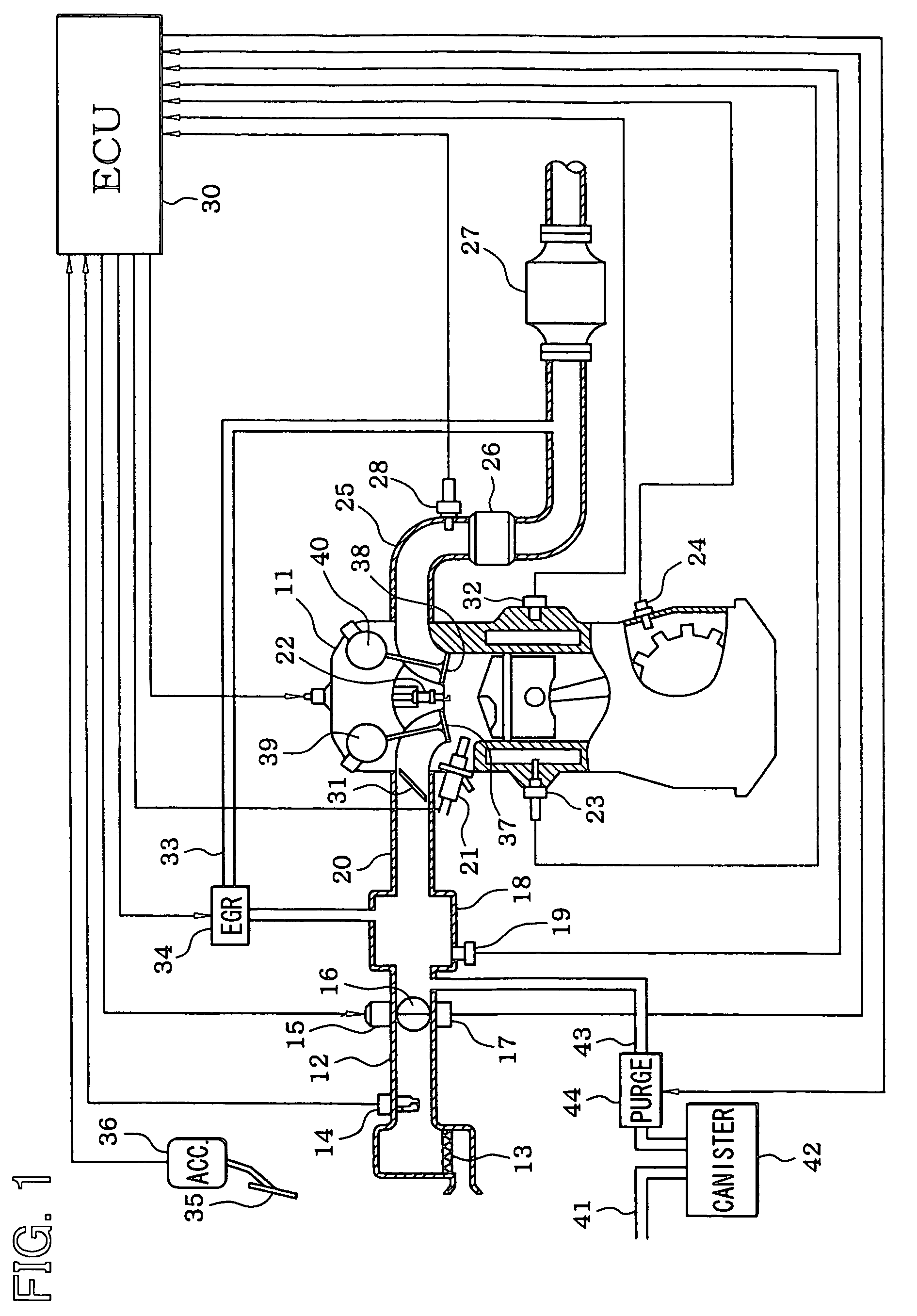
[0033]Referring to FIG. 1, an engine control system according to a first example embodiment of the present invention is illustrated. An air cleaner 13 is provided at the upstream-most portion of an intake pipe 12 of an in-cylinder injection internal combustion engine (in-cylinder injection engine) 11. An airflow meter 14 for measuring an intake air amount is provided downstream of the air cleaner 13. A throttle valve 16, the opening degree of which is regulated by a motor 15, and a throttle opening degree sensor 17 for measuring the opening degree of the throttle valve 16 (throttle opening degree) are provided downstream of the airflow meter 14.

[0034]A surge tank 18 is provided downstream of the throttle valve 16. An intake pipe pressure sensor 19 for measuring an intake pipe pressure is provided at the surge tank 18. The surge tank 18 is provided with an intake manifold 20 for introducing air into respective cylinders of the engine 11. Airflow control valves 31 of the respective cy...


PUM


Abstract

A fuel injection controller of an in-cylinder injection engine determines that a combustion state has deteriorated and executes a split injection for injecting fuel in split amounts into each cylinder in multiple injection events in a cycle of the cylinder if it is determined that a combustion fluctuation is greater than a predetermined determination value during operation of the engine. The fuel injection controller increases a ratio of an injection amount of the first injection event in the split injection and lengthens an injection interval between the injection events as the combustion fluctuation increases. Thus, a wet amount of the injected fuel is reduced to expedite atomization of the injected fuel and to homogenize an in-cylinder mixture gas. As a result, the combustion state is improved.

Description

CROSS REFERENCE TO RELATED APPLICATION[0001]This application is based on and incorporates herein by reference Japanese Patent Application No. 2005-130999 filed on Apr. 28, 2005.BACKGROUND OF THE INVENTION[0002]1. Field of the Invention[0003]The present invention relates to a fuel injection controller for an in-cylinder injection internal combustion engine that injects fuel directly into a cylinder.[0004]2. Description of Related Art[0005]In recent years, a demand for an in-cylinder injection engine (direct injection engine) having features of low fuel consumption, low exhaust emission and high output has increased rapidly. An in-cylinder injection engine, as described in JP patent No. 3186373, for example, performs a split injection for injecting fuel in split amounts into a cylinder in multiple injection events in an intake stroke during a low rotation period. Thus, even in a state in which an intake flow rate decreases during the low rotation period, an in-cylinder mixture gas, i....

Claims


Application Information

Patent Timeline
Patent Type & Authority Patents(United States)
IPC IPC(8): F02B3/00F02B5/00
CPCF02D41/1498F02D41/221F02D41/40F02D41/403F02D35/023F02D41/003F02D41/006F02D41/0065F02D41/047F02D2041/001F02D2041/0015F02D2200/0602Y02T10/44F02D35/021Y02T10/40
Inventor FUKASAWA, OSAMU
Owner DENSO CORP
Why Eureka
Try Eureka