
Heat and cold storage multistage tower with application of PCM

a technology of heat and cold storage and multi-stage towers, applied in the field of heat or cold management systems, can solve the problems of high specific cost of stored thermal energy, high technology cost, and patents that do not provide a construction of heat or cold storage, and achieve the effect of facilitating uniform distribution of h

Inactive Publication Date: 2007-05-29
LEVIN ALEXANDER
View PDF16 Cites 17 Cited by
  • Summary
  • Abstract
  • Description
  • Claims
  • Application Information

AI Technical Summary

Benefits of technology

"The invention proposes a heat or cold storage tower with a PCM (phase change material) in the form of thin layers placed in flat rigid containers. The PCM can be in the form of ceramic, glass, or sulfur concrete, and can be open or partially closed at the bottom. The heat or cold storage tower can have a distributor and redistributor to ensure uniform distribution of the PCM. The flat rigid containers can have open or sealed internal channels, and can be filled with different PCMs with gradually increasing melting points. The PCMs can be water or aqueous solutions, and can contain fillers or nucleating agents to improve thermal conductivity. The heat or cold storage tower can have support plates and auxiliary plates with recesses for drainage of the heat transfer fluid. The flat rigid containers can have corrugations or dimples on their surfaces to facilitate uniform distribution of the heat transfer fluid. The second version of the flat rigid container has ceramic blocks with open channels, which can be covered with wire gauze to reduce hydrodynamic interaction between the drops of the heat transfer fluid and the PCM."

Problems solved by technology

However, this technology is very expensive and resulting specific cost of stored thermal energy is usually high.
However, these patents do not provide a construction of a heat or cold storage, which is based on usage of ceramics or glass containers for their filling with PCM.

Method used


Image

  • Heat and cold storage multistage tower with application of PCM
  • Heat and cold storage multistage tower with application of PCM
  • Heat and cold storage multistage tower with application of PCM

Examples


Embodiment Construction

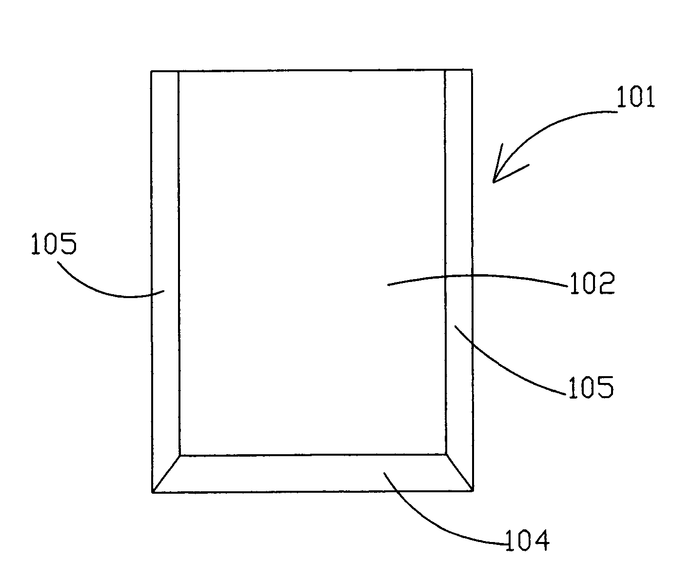
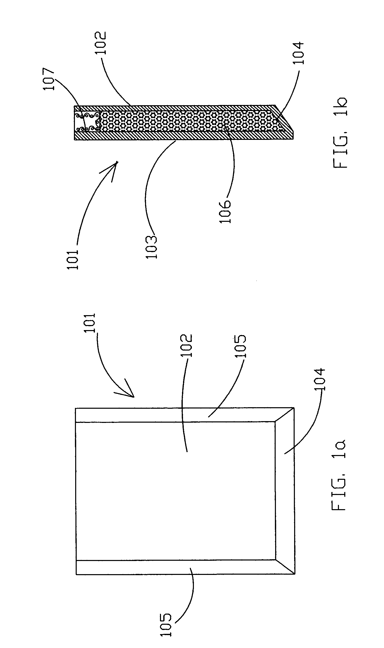
[0053]FIG. 1a and FIG. 1b show a front view and a cross-section of a flat rigid container, which is open at the top. This flat rigid container 101 comprises a front wall 102, a rear wall 103, a lower face plane 104 and two lateral face planes 105. The internal space of the flat rigid container 101 is filled with PCM 106. Wire gauze 107 is installed in the upper section of the internal space of the flat rigid container 101 above the layer of PCM 106.

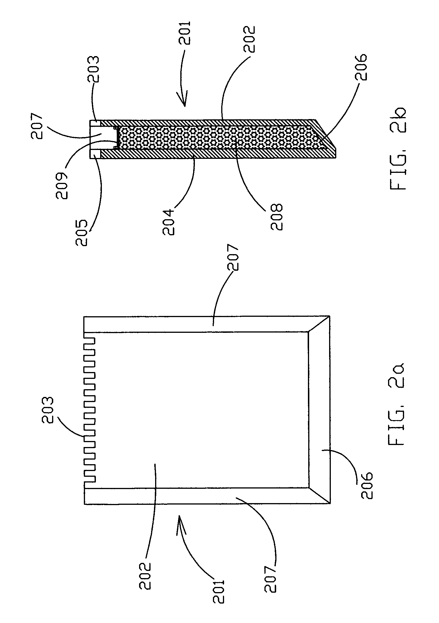
[0054]FIG. 2a and FIG. 2b show a front view and a cross-section of a flat rigid container, which is open at the top and the walls of this flat rigid container are provided with toothed edges. This flat rigid container 201 comprises a front wall 202 with teeth 203, a rear wall 204 with teeth 205, a lower face plane 206 and two lateral face planes 207. The internal space of the flat rigid container 201 is filled with PCM 208. Wire gauze 209 is installed in the upper section of the internal space of the flat rigid container 201 above the lay...


PUM

PropertyMeasurementUnit
pressureaaaaaaaaaa
thermal conductivityaaaaaaaaaa
widthaaaaaaaaaa

Abstract

A heat management system include including application of phase change materials (PCM). A heat or cold storage multistage tower has a housing with a multistage system of flat rigid container. A significant fraction of internal space of each container is filled with PCM; these containers are fabricated from ceramics, glass, glass ceramics or sulfur concrete. Another version of the heat or cold storage tower is based on application of multi-channel blocks from ceramics, glass, glass ceramics or sulfur concrete; the parallel internal vertical channels of the blocks are open and sealed at their bottoms alternatively, and the channels with the sealed bottoms are filled partially with PCM. The tower achieves effective heat transfer between a heat transfer fluid (HTF) and PCM in the processes of charging and discharging of the containers with heat or cold.

Description

BACKGROUND OF THE INVENTION[0001]This invention relates to the area of heat or cold management systems and, specifically, to the heat or cold management systems, which include application of phase change materials (PCM).[0002]The main field of usage of these heat or cold management systems is thermal solar power plants that apply some types of optical concentrators of solar radiation in order to achieve sufficiently high temperature of heat transfer medium flowing in the receiver of a solar collector. However, the proposed heat management system can be used in other fields, for example, for decrease of energy consumption in thermal treatment of metals.[0003]Another important application of the proposed heat or cold management system is cold accumulation in the form of ice in large air-conditioning systems in night-time.[0004]It is known, that heat or cold can be stored in materials in the forms of sensible heat or latent heat. A material storing sensible heat can be in liquid form (...

Claims


Application Information

Patent Timeline
Patent Type & Authority Patents(United States)
IPC IPC(8): F28D5/02
CPCF28D20/021F28D20/023Y02E60/145Y02E60/14
Inventor LEVIN, ALEXANDER
Owner LEVIN ALEXANDER
Learn More