Steam turbine

a steam turbine and steam technology, applied in the field of steam turbines, can solve the problems of elevated risk of damage and valve oscillation, and achieve the effect of reducing damage risk

Inactive Publication Date: 2007-05-29
ALSTOM TECH LTD
View PDF15 Cites 14 Cited by
  • Summary
  • Abstract
  • Description
  • Claims
  • Application Information

AI Technical Summary

Benefits of technology

[0007]In view of these disadvantages of the known valve arrangements for live steam intake, it is the object of the present invention to create a valve arrangement for controlling the live steam in-flow into a steam turbine that exhibits a reduced risk of damage, even in the reduction of rather great pressures, in particular.
[0009]The valve arrangement according to the invention, in the case of partial load operation, allows a stepwise reduction of the loss of pressure by way of the two individual control valves, that is, the converted energy in the case of throttled operation is distributed to the two or more control valves. By these means, compared to a valve arrangement with a quick-acting stop valve together with just one control valve, the stress imposed upon one individual control valve is markedly reduced. The risk of valve oscillations and potential valve damage as a consequence thereof, is reduced by these means. The first control valve can, in the case of the arrangement according to the invention, assume the safety function of a quick-acting stop valve, so that the safety provided by this valve arrangement is not diminished in comparison with the state of the art.
[0010]The valve arrangement according to the invention can, in the case of steam turbines, be used, either with or without a control stage. In the case of steam turbines without a control stage, it reduces, in particular, the relatively high stresses imposed on the control valves. Furthermore, it lends itself well to steam turbines with fixed pressure operation, and in operation with variable live steam pressure. Once again, the valve arrangement according to the invention is particularly effective in steam turbines without a control stage and especially in the case of those in fixed pressure operation for the reduction of stress-related valve oscillations.
[0012]The valve arrangement yields the advantage that the problems of the potential valve oscillations, particularly in the case of steam turbines without a control step and in the case of fixed pressure operation, are solved by a simple arrangement of a single valve type, without incurring any losses in terms of safety. Furthermore, it renders the advantage possible, in that known control valves and actuating drives can be used. The same drive is used, preferably, for all control valves.

Problems solved by technology

The stop valves assure safety for the live steam in-flow, but they cannot assume any throttling function.
If a steam turbine is operated at fixed pressure, elevated stresses and critical pressure conditions arise in the control valves, which cause correspondingly elevated valve oscillations and an elevated risk of damage.

Method used


Image

  • Steam turbine
  • Steam turbine
  • Steam turbine

Examples


Embodiment Construction

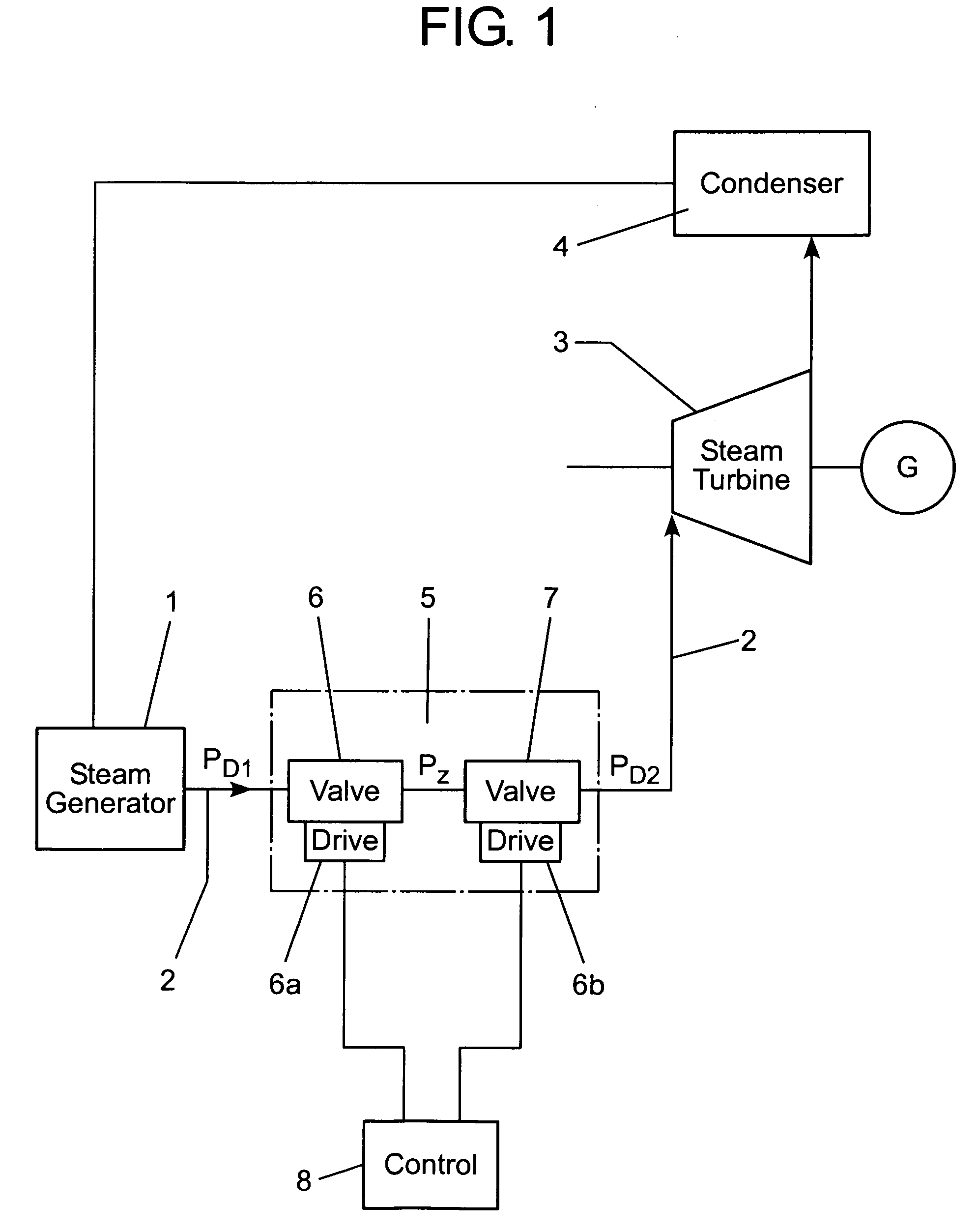
[0017]FIG. 1 shows, schematically, a steam turbine facility with a steam generator 1, which is connected, by means of a live steam feed line 2, with a steam turbine 3. The steam turbine 3 is coupled to a generator G. The steam, whose pressure is released in the turbine, is led to a condenser 4, whereby the condensation that arises there is again led to the facility's water-steam circuit. Feed line 2 exhibits a valve arrangement 5 for the purpose of controlling the live steam pressure in accordance with a prescribed operational load. Here, in the direction of flow, the valve arrangement exhibits a first control valve 6 and a second control valve 7, which are arranged in series. The control valves 6 and 7 each exhibit an actuating drive 6a or 6b, respectively, which are connected with a open-loop or closed-loop control apparatus 8. Both control valves can be placed in a fully closed position, a fully open position, or any arbitrary partially open position by means of the control appar...


PUM


Abstract

The invention relates to a steam turbine comprising a valve arrangement for regulating the admission of live steam into the turbine consisting of two serially connected regulating valves. The two regulating valves enable a step-by-step separation of the live steam and ensure operational security in the case of a partial load operation of the turbine. Said valve arrangement is particularly suitable for steam turbines devoid of regulating steps in a fixed-pressure operation mode.

Description

FIELD OF THE INVENTION[0001]The invention relates to a steam turbine, and especially a valve arrangement for the admission of live steam to the steam turbine.BACKGROUND OF THE INVENTION[0002]Steam turbines are known in which the in-flow of live steam is controlled by nozzle regulation by means of a control stage, also called the first turbine stage. Such a control stage exhibits, for example, admission sectors of varying sizes, to which the live steam is fed, in each case, by way of a live steam feed in-flow with several control valves. As a safety measure, a quick-acting stop valve is arranged in series prior the control valves. Such an arrangement is disclosed, for example, in the sales documentation of ABB Power Generation, Description No. HTGD N 12 018.[0003]These steam turbines are typically operated at a live steam pressure that is fixedly set by the steam generator's operating parameters for all of the steam turbines' operating loads. As a result of various settings of the th...

Claims


Application Information

Patent Timeline
Patent Type & Authority Patents(United States)
IPC IPC(8): F01D17/10F01D17/08F01D17/14F01D17/18F01K7/16
CPCF01D17/08F01D17/10F01D17/145F01D17/18F01K7/165Y10T137/87917
Inventor SUTER, FRANZ
Owner ALSTOM TECH LTD
Why Eureka
Try Eureka