

Laser scanning microscope
- Summary
- Abstract
- Description
- Claims
- Application Information
AI Technical Summary
Benefits of technology
Problems solved by technology
Method used
Image

Examples
first embodiment
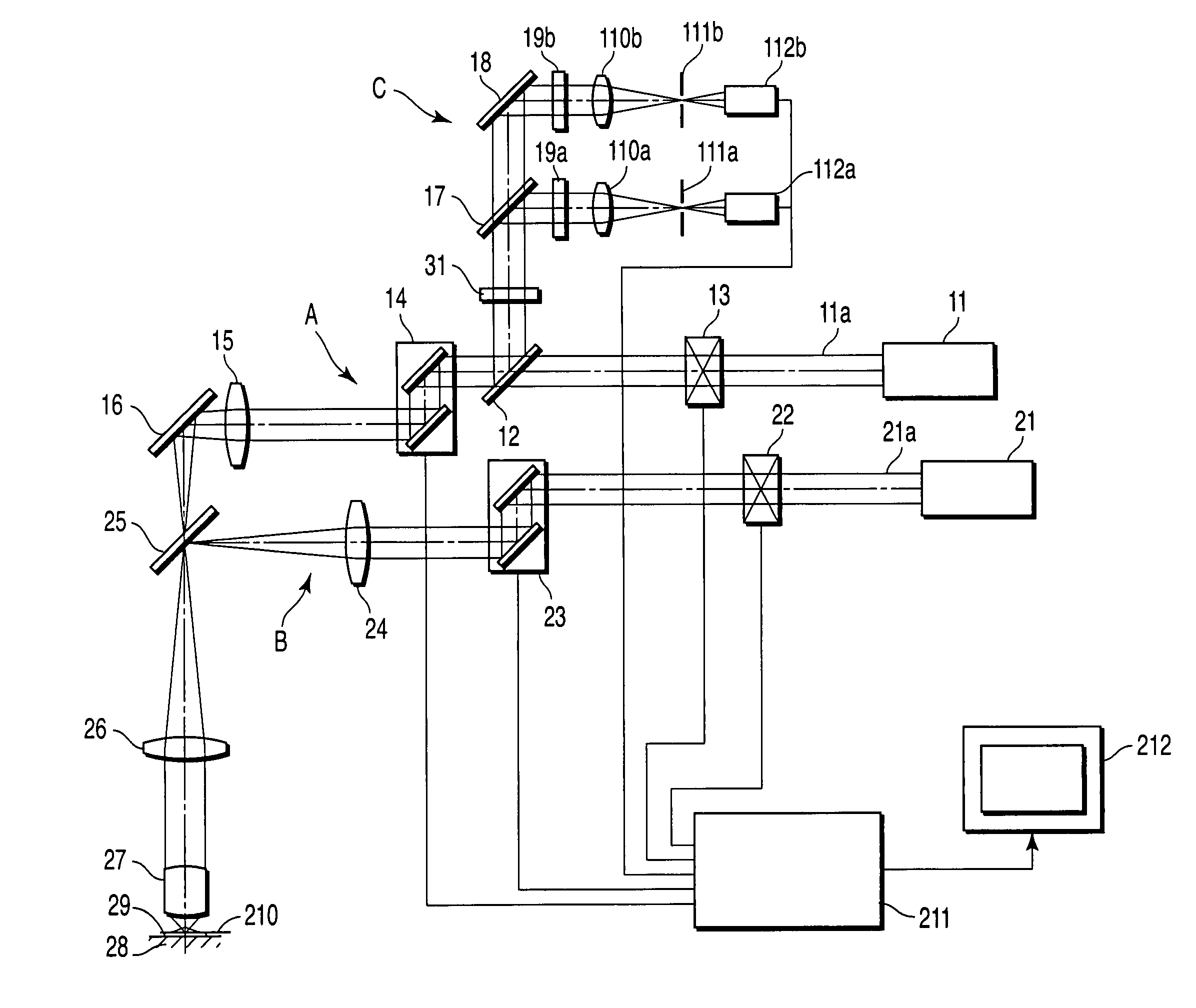
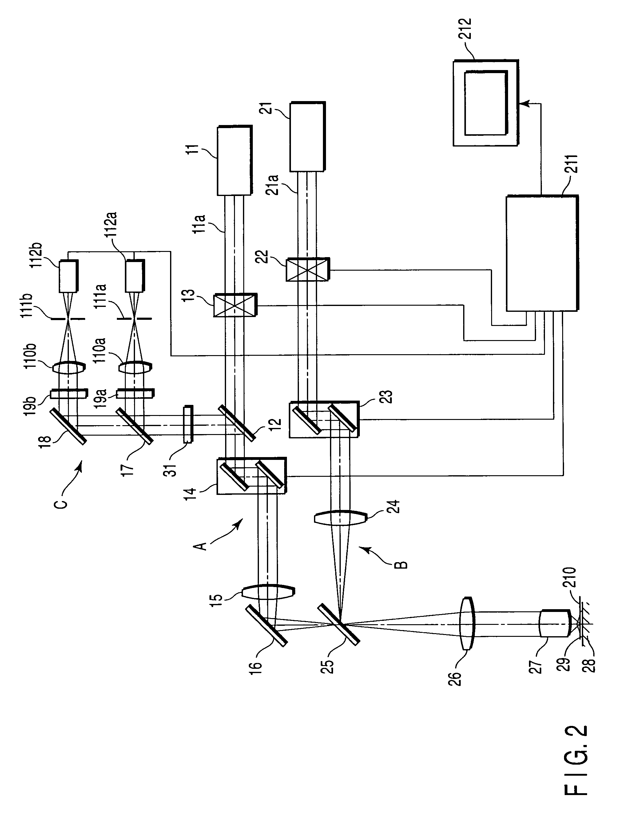
[0023]the present invention will be described. FIG. 2 is a diagram of a laser scanning microscope according to the present invention.
[0024]The laser scanning microscope includes a first optical scanning system A and second optical scanning system B. The first optical scanning system A is an optical system for observation, which scans the surface of a sample 29 with a laser light 11a outputted from a first laser unit 11. The second optical scanning system B is an optical system for expressing a peculiar phenomenon in a specific portion of the sample. That is, the second optical scanning system B irradiates an arbitrary position of the sample 29 with a laser light 21a outputted from a second laser unit 21 to release a caged reagent.
[0025]The first optical scanning system A includes the first laser unit 11, dichroic mirror 12, first laser shutter 13, first optical scanning unit 14, pupil projection lens 15, and mirror 16. Furthermore, an optical detection system C is disposed in a bran...
second embodiment
[0058]In the second embodiment, a UV pulse laser 34 and an IR pulse laser 35 whose wavelength can be varied and which can cause the two photon excitation phenomenon are used in the laser of the second optical scanning system B. Moreover, these lasers 34, 35 can be selected and used by controlling the opening / closing of laser shutters 36 and 37. The dichroic mirror 25 is disposed in a position where the optical axis of the laser light 11a from the first optical scanning system A and that of laser light 34a or 35a from the second optical scanning system B are synthesized. At least one dichroic mirror 25 is disposed in an electromotive turret 32 in which a plurality of dichroic mirrors can be disposed.
[0059]Further to cut off the laser light 34a or 35a from the laser unit of the second optical scanning system B, the laser cut filter 31 is disposed on the optical path of the optical detection system C. At least one laser cut filter 31 is disposed in an electromotive turret 33 in which a...
third embodiment
[0083]As described above, in the third embodiment, the first optical scanning system A includes the image forming lens 41, and the second optical scanning system B includes the image forming lens 43. Therefore, the laser light which has passed through the image forming lenses 41, 43 forms the parallel light, and the optical axis of the first optical scanning system A can easily be matched with that of the second optical scanning system B.
[0084]That is, a luminous flux of a connecting portion of the laser scanning microscope D including the first optical scanning system A with respect to the illuminative light introduction apparatus E including the second optical scanning system B is the parallel light. Therefore, optical axis alignment is facilitated in connecting the laser scanning microscope D to the illuminative light introduction apparatus E.
[0085]Moreover, the first optical scanning system A is constituted as the laser scanning microscope D, and the second optical scanning syst...
PUM
 Abstract
Description
Claims
Application Information