RFID device and method of forming

a technology of rfid devices and forming methods, applied in the direction of burglar alarm mechanical actuation, protective material radiating elements, instruments, etc., can solve the problems of large area reducing the accuracy required for placement of ics during manufacture, serious limitations in high-speed manufacturing of ic placement and mounting, and other substantial manufacturing problems to be solved

Inactive Publication Date: 2007-05-29
AVERY DENNISON CORP
View PDF82 Cites 135 Cited by
  • Summary
  • Abstract
  • Description
  • Claims
  • Application Information

AI Technical Summary

Problems solved by technology

The larger area reduces the accuracy required for placement of ICs during manufacture while still providing effective electrical connection.
IC placement and mounting are serious limitations for high-speed manufacture.
However, other substantial manufacturing problems must be solved in order to provide an efficient inlay production process using interposers.
Another problem to be solved in producing inlays using interposers is the reliable high speed mechanical and electrical coupling of the interposers (and interposer leads) to antennas.

Method used


Image

  • RFID device and method of forming
  • RFID device and method of forming
  • RFID device and method of forming

Examples


Embodiment Construction

RFID Inlays—General Considerations

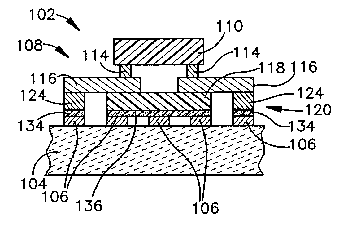
[0071]By way of overview, the present invention involves structures and method for operatively coupling parts of an RFID inlay together. Specifically, the invention relates to conductive or capacitive connections between an RFID antenna and an interposer that is in turn contains a chip, such as an integrated circuit chip. The conductive connection may include conductive bumps attached to the interposer, and / or may include conductive traces, such as a conductive ink traces. The capacitive connection may involve putting the antenna and the interposer into close proximity, to allow capacitive coupling between the antenna and the interposer. The capacitive and conductive connections provide a convenient, fast, and effective way to operatively couple antennas and interposers.

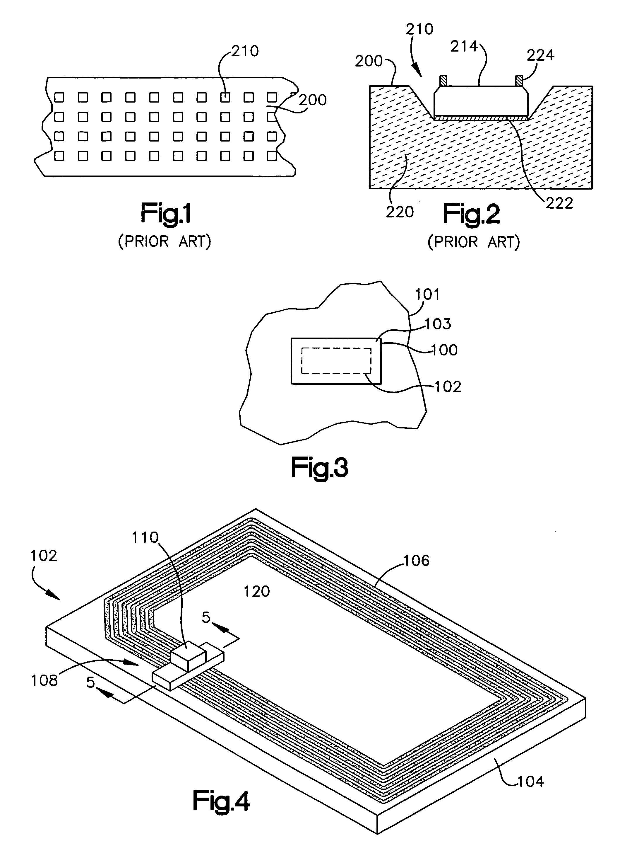
[0072]Referring initially to FIG. 3, an RFID tag or label 100 is adhered or otherwise coupled to an object 101. The RFID tag or label 100 includes an RFID inlay 102 and a printable f...


PUM

PropertyMeasurementUnit
thicknessaaaaaaaaaa
thicknessaaaaaaaaaa
thicknessaaaaaaaaaa

Abstract

A radio frequency identification (RFID) inlay includes an electrical connection between a chip and an antenna. The electrical connection includes conductive interposer leads and a capacitive connection. The capacitive connection may involve putting the antenna and the interposer leads into close proximity, with dielectric pads therebetween, to allow capacitive coupling between the antenna and the interposer leads. The dielectric pads may include a non-conductive adhesive and a high dielectric material, such as a titanium oxide. The connections provide a convenient, fast, and effective way to operatively couple antennas and interposers. The RFID inlay may be part of an RFID lable or RFID tag.

Description

[0001]This application is a continuation-in-part of U.S. application Ser. No. 10 / 334,290, filed Dec. 31, 2002, now U.S. Pat. No. 6,940,408, and is also a continuation-in-part of PCT Application No. PCT / US03 / 41534, filed Dec. 31, 2003. Both of the above applications are hereby incorporated by reference in their entireties.BACKGROUND OF THE INVENTION[0002]1. Field of the Invention[0003]This invention relates to the field of radio frequency identification (RFID) tags and labels, and to particular configuration of such devices and methods of manufacturing such devices.[0004]2. Description of the Related Art[0005]RFID tags and labels have a combination of antennas and analog and / or digital electronics, which may include for example communications electronics, data memory, and control logic. RFID tags and labels are widely used to associate an object with an identification code. For example, RFID tags are used in conjunction with security-locks in cars, for access control to buildings, an...

Claims


Application Information

Patent Timeline
Patent Type & Authority Patents(United States)
IPC IPC(8): H01Q13/14G06K19/077H01Q1/22H01Q1/38H01Q7/00
CPCG06K19/07745G06K19/07752G06K19/07756H01Q1/22H01Q1/2225H01Q1/38H01Q7/00G06K19/07749Y10T29/49124H01L2224/16H01L2924/01046H01L2924/01079H01L2924/3011H01L2924/1461H01L2924/00G06K19/077H01Q1/24
Inventor FERGUSON, SCOTT WAYNEEDWARDS, DAVID N.LIU, PEIKANGMUNN, JASONFORSTER, IAN J.LINDER, SAMUEL A.WEAKLEY, THOMAS CRAIGPULESTON, DAVIDKENNEDY, STEVEN C.DANG, CHRISTINE U.
Owner AVERY DENNISON CORP
Why Eureka
Try Eureka