Electronic imaging system having a sensor for correcting perspective projection distortion

a technology of perspective distortion and electronic imaging system, which is applied in the field of imaging system for capturing nonplanar projections, can solve the problems of requiring a significant portion of the total computational time of the system for the step of geometrically warping images to compensate for perspective distortion, and the distortion becomes immediately apparen

Inactive Publication Date: 2007-05-29
MONUMENT PEAK VENTURES LLC
View PDF10 Cites 24 Cited by
  • Summary
  • Abstract
  • Description
  • Claims
  • Application Information

AI Technical Summary

Benefits of technology

[0010]The present invention is directed to overcoming one or more of the problems set forth above. Briefly summarized, according to one aspect of the present invention, an electronic imaging system for capturing an image of a scene includes an optical system for producing an optical image of the scene, an imaging sensor having a surface in optical communication with the optical system, and a plurality of imaging elements distributed on the surface of the imaging sensor according to a distribution representable by a nonlinear function in which the relative density of the distributed imaging elements is greater toward the center of the sensor. Such a distribution provides physical coordinates for the imaging elements corresponding to a projection of the scene onto a non-planar surface, thereby compensating for perspective distortion of the scene onto the non-planar surface and alleviating the need to perform geometric warping of the images after they have been captured.

Problems solved by technology

This distortion becomes immediately apparent when attempting to stitch subsequent images together.
Since it is extremely difficult and expensive to manufacture sensors that are spherical or cylindrical in shape, compensation for the perspective distortion is generally performed after the image has been captured.
In some image stitching systems, specifically systems that construct composite digital images in real time, or systems that construct a large sequence of composite digital images (e.g., a system that stitches together images from video sequences to form a composite video sequence), the step of geometrically warping the images to compensate for the perspective distortion requires a significantly large portion of the total computational time of the system.
Another type of distortion that occurs in most camera systems (especially those with wide-angle lenses) is lens distortion.
In addition, lens irregularities and aberrations can induce local distortions in different areas of the image plane.
However, neither of these patents are directly applicable to systems compensating for perspective distortion.

Method used


Image

  • Electronic imaging system having a sensor for correcting perspective projection distortion
  • Electronic imaging system having a sensor for correcting perspective projection distortion
  • Electronic imaging system having a sensor for correcting perspective projection distortion

Examples


Embodiment Construction

[0023]Because imaging systems employing electronic sensors are well known, the present description will be directed in particular to elements forming part of, or cooperating more directly with, apparatus in accordance with the present invention. Elements not specifically shown or described herein may be selected from those known in the art. Certain aspects of the embodiments to be described may be provided in software. Given the system as shown and described according to the invention in the following materials, software not specifically shown, described or suggested herein that is useful for implementation of the invention is conventional and within the ordinary skill in such arts.

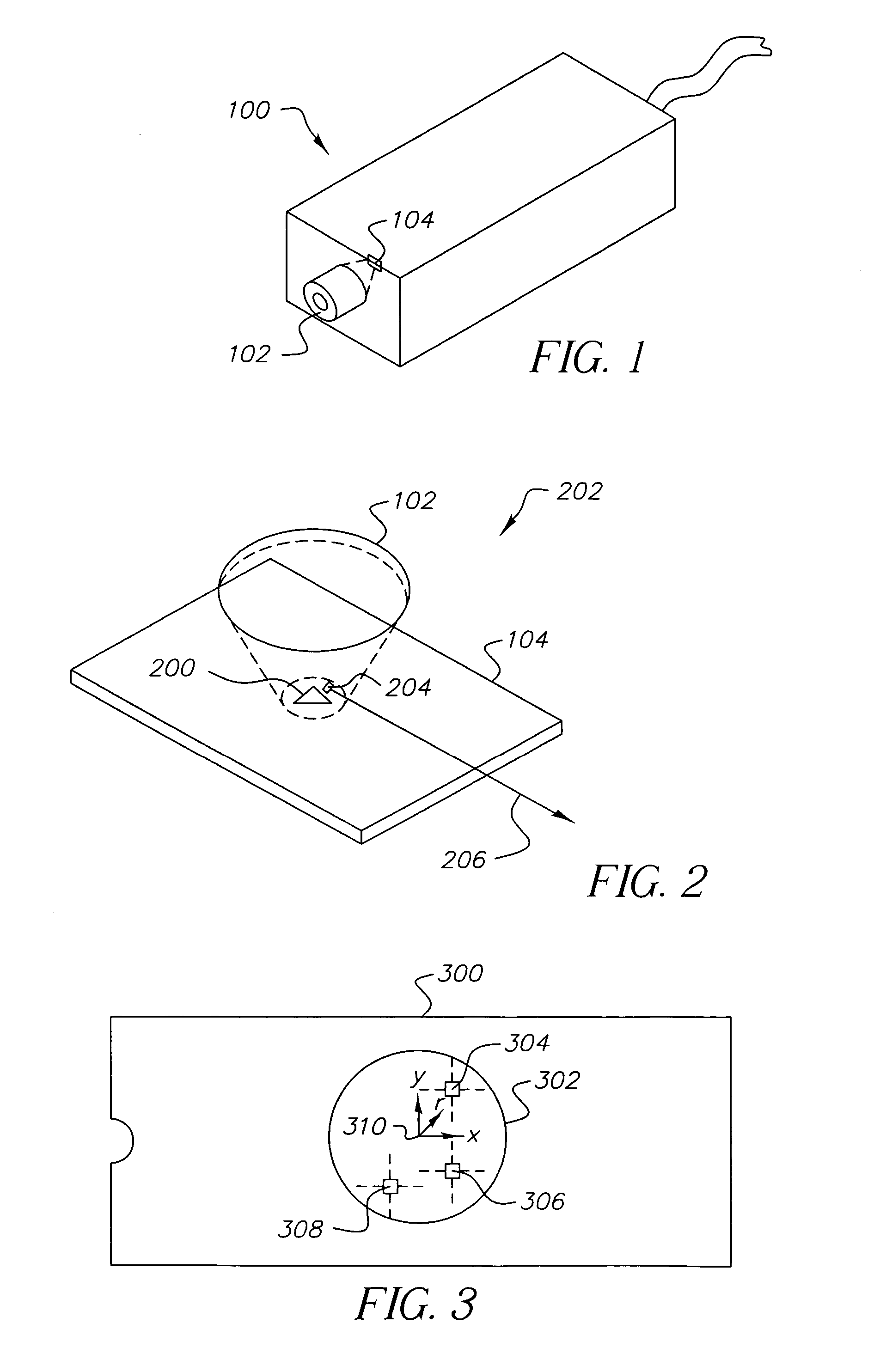
[0024]FIG. 1 shows a pictorial diagram of a camera used in conjunction with one embodiment of the present invention. Camera 100 includes an optical system, including a lens 102, that projects an image of the scene in front of camera 100 onto an imaging sensor 104. This sensor 104 includes an array of indi...


PUM


Abstract

An electronic imaging system for capturing an image of a scene includes an optical system for producing an optical image of the scene, an imaging sensor having a surface in optical communication with the optical system, and a plurality of imaging elements distributed on the surface of the imaging sensor according to a distribution representable by a nonlinear function in which the relative density of the distributed imaging elements is greater toward the center of the sensor. Such a distribution provides physical coordinates for the imaging elements corresponding to a projection of the scene onto a non-planar surface, thereby compensating for perspective distortion of the scene onto the non-planar surface and alleviating the need to perform geometric warping of the images after they have been captured.

Description

FIELD OF THE INVENTION[0001]The present invention relates generally to imaging systems and, in particular, to an imaging system for capturing non-planar projections of a scene.BACKGROUND OF THE INVENTION[0002]Conventional cameras provide photographs of real world scenes with a limited field of view of the scene being photographed. In many scenarios, the photographer desires an image corresponding to a wider field of view. Typically, the photographer can resort to two methods of generating a wide field of view image. The first method is to capture the wide field of view image directly; e.g., with a wide-angle lens, or with a specialized system of mirrors to reflect the wide field of view onto the sensor. The second method is to capture a collection of images, each image having a narrower field of view, and then use one of a variety of digital image stitching techniques to combine the narrow field of view images into a composite digital image. The composite digital image will appear t...

Claims


Application Information

Patent Timeline
Patent Type & Authority Patents(United States)
IPC IPC(8): H04N5/335H04N5/225H04N7/00H04N5/217H04N5/262H04N5/369
CPCH04N5/2253H04N5/23238H04N5/2628H04N23/54H04N23/698
Inventor CAHILL, NATHAN D.GALLAGHER, ANDREW C.
Owner MONUMENT PEAK VENTURES LLC
Why Eureka
Try Eureka