Method of producing a printing plate on a cylindrical printing-plate carrier in a rotary printing press

Inactive Publication Date: 2007-05-29
MANROLANAD AG
View PDF4 Cites 2 Cited by
  • Summary
  • Abstract
  • Description
  • Claims
  • Application Information

AI Technical Summary

Benefits of technology

[0017]It is an object of the present invention to provide quality assurance in rotary printing with regard to the printing or transfer characteristic curves, in particular in lithographic offset printing, which brings about the compensation of positional changes of printing cylinders owing to deflection in a cost-effective and flexible manner and without mechanical compensation measures.

Problems solved by technology

A set-up where the transfer pressure is too low yields non-uniform transport of ink or damping solution, because of the tolerances of circular running and cylindricity.
A setting where the transfer pressure is too high prematurely wears the cylinder surface, because of internal friction and pressure overload.
A further problem for quality assurance results from the requirement for higher and higher productivity, for example as a result of attempts to produce the most lightweight and cost-effective cylinders.
The length / thickness ratio of the printing cylinder and its relative stiffness with regard to deflection therefore become less and less favourable.
The consequence of this is that during printing operation the shape and position of the printing cylinders in relation to one another may change in an undesirable way, that is to say the printing cylinders deflect.
This pressure becomes non-uniform when viewed over the cylinder width.
The effect described therefore leads to a printing characteristic curve which changes in an undesired manner as viewed over the cylinder width.
However, these measures are currently viewed as being too complicated and too expensive.

Method used


Image

  • Method of producing a printing plate on a cylindrical printing-plate carrier in a rotary printing press
  • Method of producing a printing plate on a cylindrical printing-plate carrier in a rotary printing press
  • Method of producing a printing plate on a cylindrical printing-plate carrier in a rotary printing press

Examples


Embodiment Construction

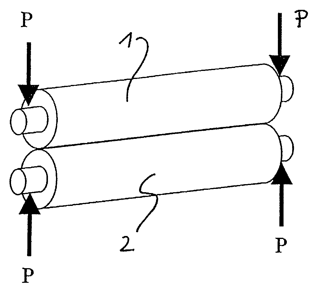
[0025]The particular advantage of the method according to the present invention resides in the fact that the intended quality assurance of the edition printing is consequently cost-effective and flexible and, in particular, can be adapted to different printing set-ups (FIG. 1a, P—P of two cylinders, for example a printing-plate cylinder 1 and a blanket cylinder 2) and the associated cylinder deflections, without making constructional measures necessary.

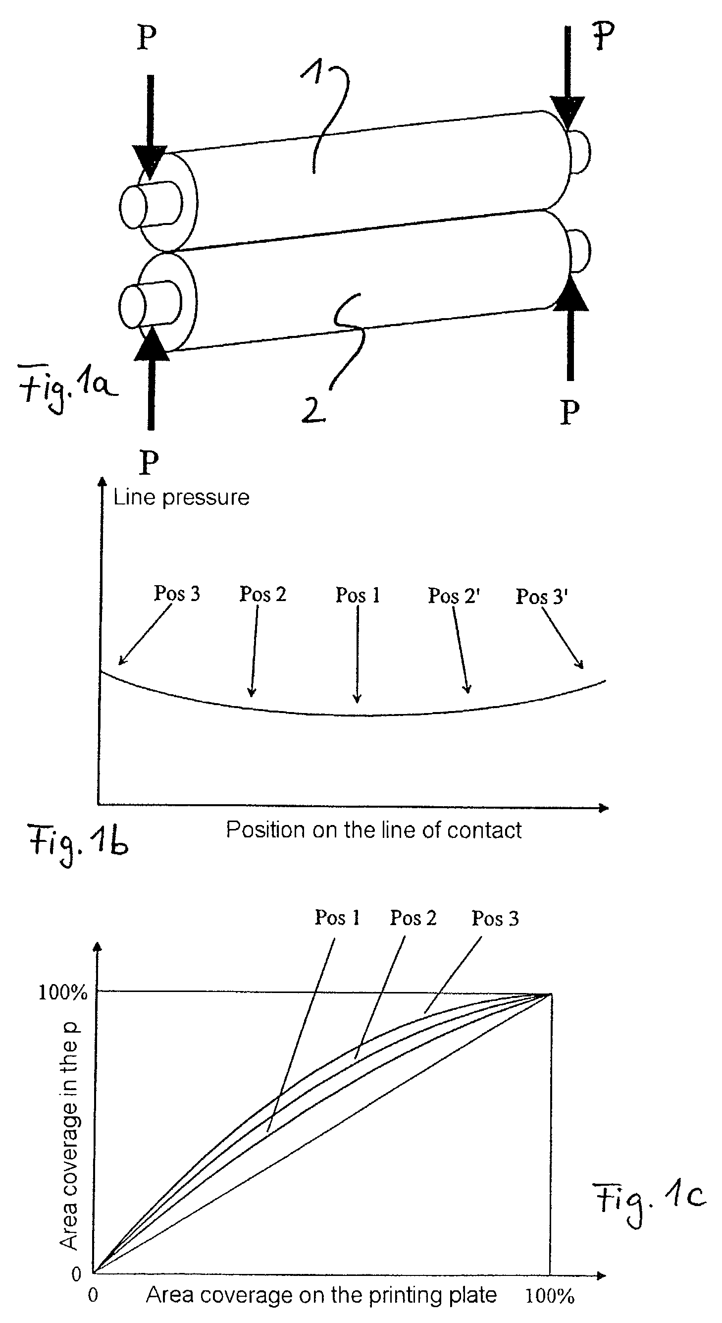
[0026]Furthermore, FIG. 1b shows the consequences of the undesired positional change (deflection) of the two cylinders 1 and 2 of FIG. 1a in relation to each other during printing operation. The transfer pressure P—P becomes non-uniform over the cylinder width, that is to say a line pressure which is irregular over the cylinder width is produced. In FIG. 1b, position 1 (Pos 1) shows approximately the middle of the cylinder width, position 3 (Pos 3) shows the left-hand edge region and position 3′ (Pos 3′) shows the right-hand edge regi...


PUM


Abstract

A method of producing a printing plate on a cylindrical printing-plate carrier includes subdividing the printing-plate carrier by computation in terms of its width and axial length into at least two circumferential subareas. Then an actual transfer characteristic curve for each subarea is determined and compared by computation with a predetermined desired printing characteristic curve for each subarea to find a deviation. The method further includes calculating a correction to compensate for each deviation; receiving a digital image data in a first data format using a raster image processor; converting the digital image data into machine-specific image data including the position and the tonal value in the form of a bitmap; applying the correction for a predetermined desired printing characteristic curve for the edition print to the machine-specific image data using the raster image processor; and supplying the corrected machine-specific image data to an imagesetting unit.

Description

PRIORITY CLAIM[0001]This application claims priority to DE 102 13 708.0 filed Mar. 27, 2002 in Germany.FIELD OF THE INVENTION[0002]The invention relates to a method of producing a printing-plate on a cylindrical printing-plate carrier in a rotary printing press, in particular in lithographic offset printing, but is not limited to that.BACKGROUND OF THE INVENTION[0003]The present inventive method utilizes a digital imagesetting system for producing a printing plate for a rotary printing press; especially an offset printing cylinder which can be written on digitally and also erased again.[0004]The printing unit may be a customary offset printing press. In such presses three cylinders, the printing-plate carrier cylinder, the blanket cylinders and the impression cylinders, collectively the printing cylinders, cooperate to create a printed image. The data to be printed, i.e. image information, has been transferred on a printing-plate carrier. Using a principle akin to immiscibility of o...

Claims


Application Information

Patent Timeline
IPC IPC(8): B41C1/02B41C1/10B41C1/00H04N1/047H04N1/06H04N1/407
CPCB41C1/1075H04N1/047H04N1/407B41P2227/70H04N1/06H04N2201/04717H04N2201/04787
Inventor SCHNEIDER, JOSEFWEICHMANN, ARMIN
Owner MANROLANAD AG
Why Eureka
Try Eureka