

System for capturing an image of the retina for identification
- Summary
- Abstract
- Description
- Claims
- Application Information
AI Technical Summary
Benefits of technology
Problems solved by technology
Method used
Image

Examples
Embodiment Construction
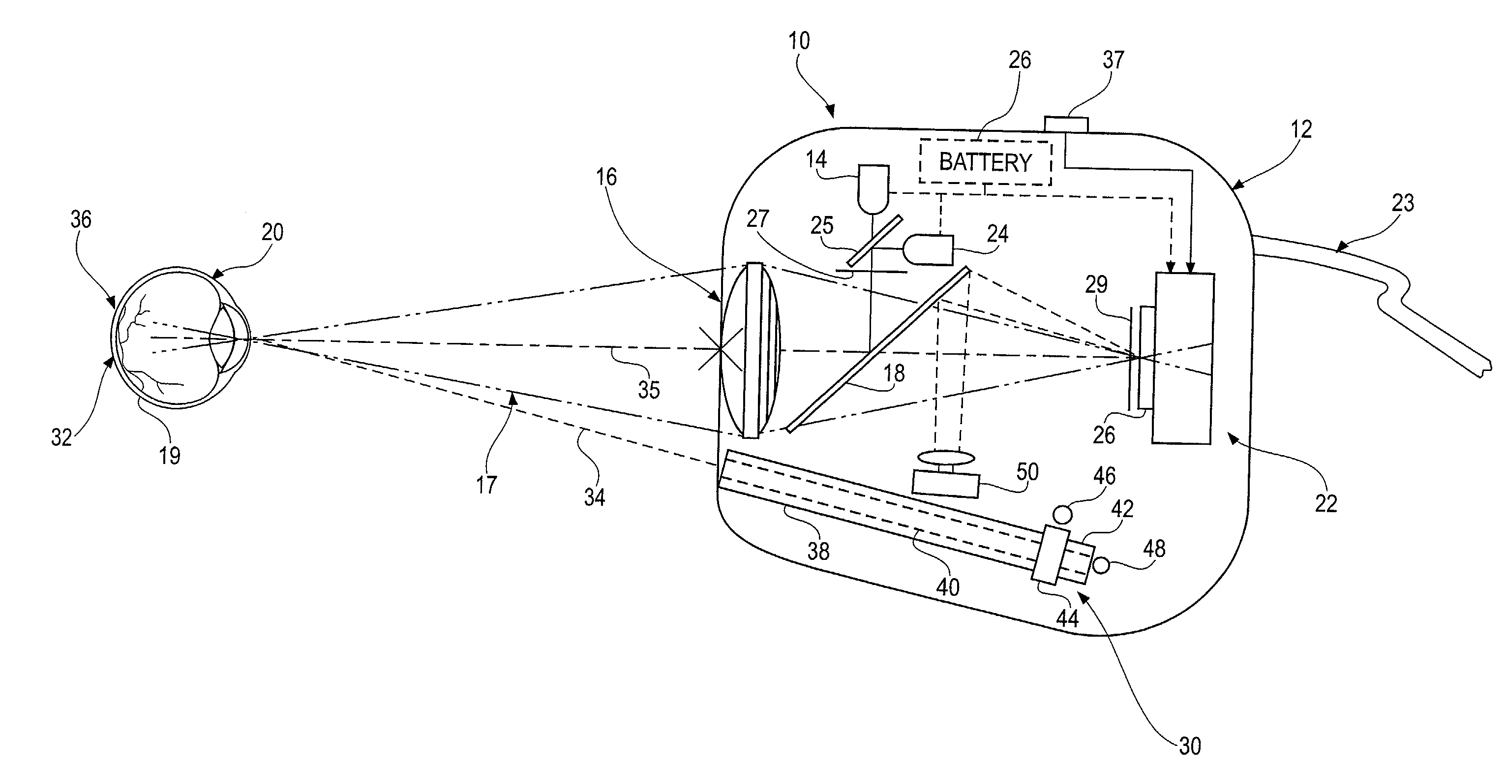
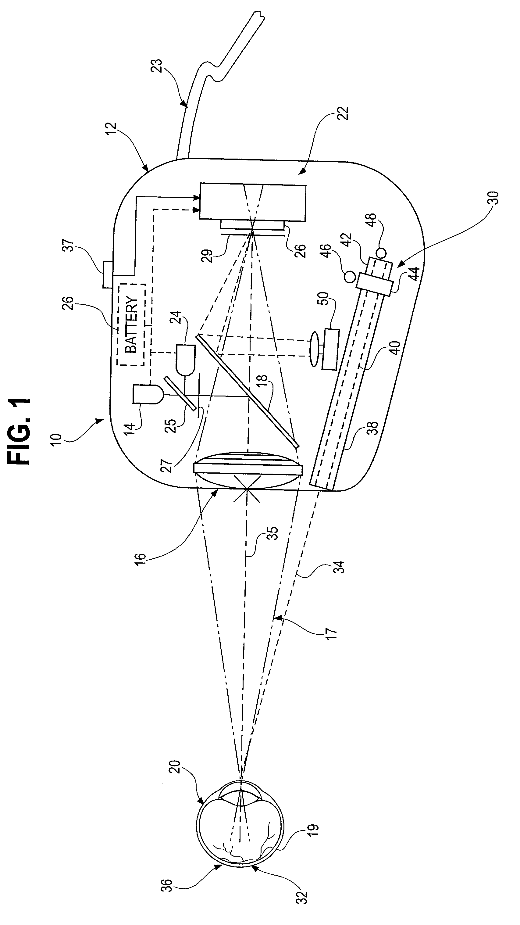
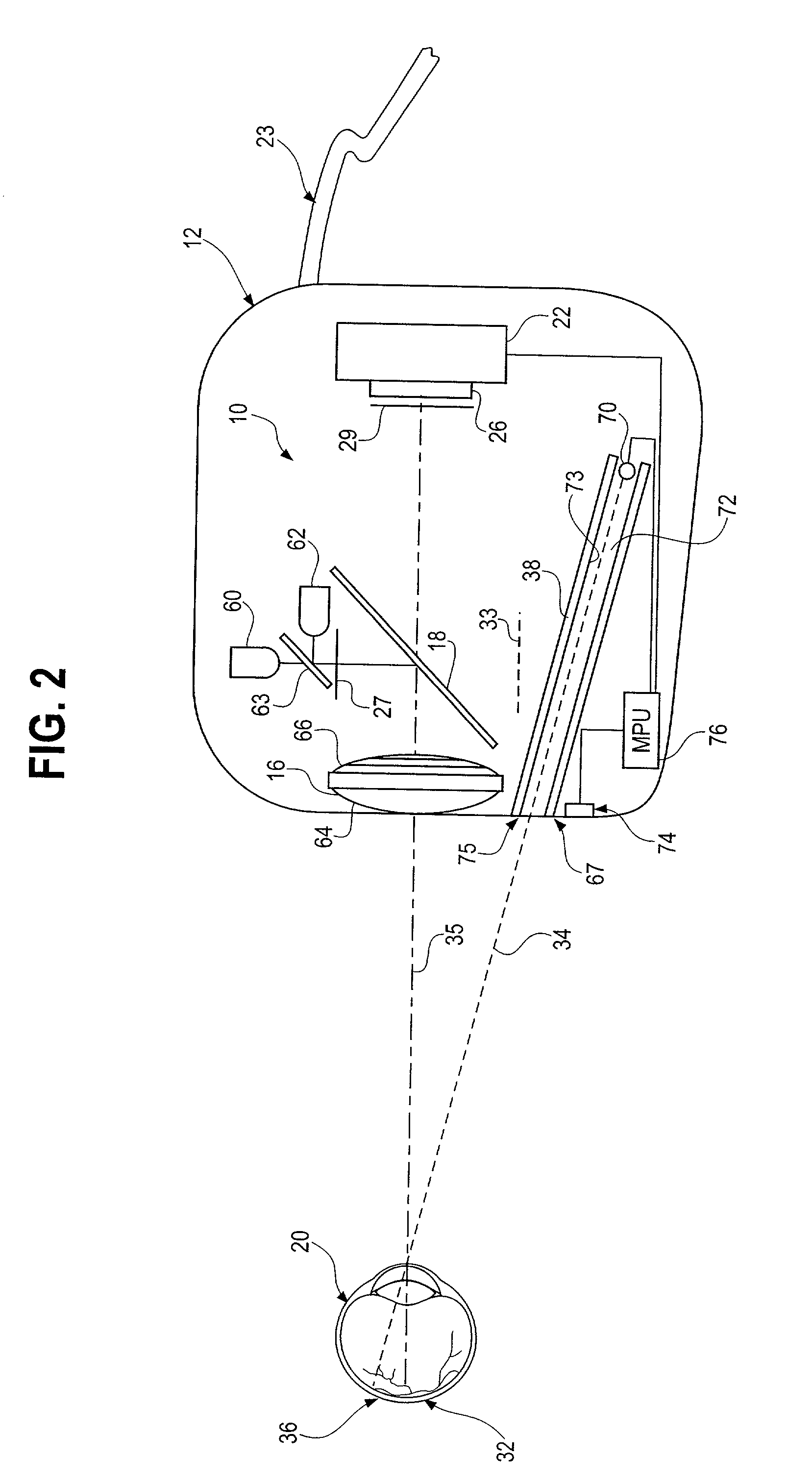
[0015]The system 10 of the present invention captures an image of an area of the retina 19 of an eye 20 and, in particular, an image of the optic disk 32 and surrounding area. It has been found that the optic disk 32 contains the smallest amount of information in the eye to uniquely identify an individual. Because the eye pivots about the optic nerve, an image of the retina centered on the optic disk is the most stable and repeatable image that can be obtained. Further, it has been found that the optic disk can be sufficiently illuminated for image analysis by a non-scanned light source resulting in a system 10 that is considerably less expensive and less complex than prior retinal identification systems. The system 10 of the present invention further has a minimal number of optical components resulting in an extremely compact device that is sufficiently small so as to be contained in a portable and / or hand held housing 12. This feature allows the system 10 of the present invention ...
PUM
 Abstract
Description
Claims
Application Information