Valve device and method for injecting a gaseous fuel

a valve device and gaseous fuel technology, which is applied in the direction of fuel supply apparatus, special fuel injection apparatus, structural/machine measurement, etc., can solve the problems of inability to design the injector to be suitable for gaseous fuel injection, the response characteristic and the scope of control options, and the comparatively slow response characteristic of the hydraulic valve, etc., to achieve accurate valve needle position control, reduce the effect of valve li

Inactive Publication Date: 2007-06-05
WESTPORT POWER
View PDF50 Cites 39 Cited by
  • Summary
  • Abstract
  • Description
  • Claims
  • Application Information

AI Technical Summary

Benefits of technology

[0019]To achieve favorable response characteristics for a valve opening that is adequately large for the injection of gaseous fuel, that is, with an adequately large valve lift, the present technique provides a combination of a direct drive, such as an actuator that is operated piezoelectrically or magnetostrictively, or if required electromagnetically to produce a displacement, and an associated transmission device disposed between the actuator and a valve. The transmission device is operative to mechanically increase the displacement received from the actuator, via the force imparted to the transmission device due to displacement of the actuator, to produce a greater valve lift in the valve. The present technique allows a simple design of the valve device, whereby rapid response characteristics and an adequately large valve opening for the injection of gaseous fuel can be achieved.
[0020]In a preferred embodiment of the valve device the transmission device comprises at least two levers, which are arranged in series in order to further increase the lift beyond the displacement produced by the actuator to actuate the valve. An advantage of this embodiment is that it allows a simple design, in which the two levers can be employed to provide a compact construction and a high transmission ratio, which is desirable for the injection of gaseous fuel.
[0023]In combination with the disclosed transmission device, compared to conventional hydraulically actuated valve devices, the disclosed valve device with an actuator driven by direct drive elements can achieve faster switching and response times, and more accurate valve needle position control, and accordingly, an advantage of this valve device is that it becomes practical to have multiple or intermittent injections of fuel during a power cycle and / or a shaping of the fuel injection behavior during the injection period (variations of the flow or the injection rate during the injection period). That is, a rapid response and a variable valve lift or opening cross section of the valve make it possible, for example, to accurately set: (a) the injection period and injection quantity; (b) the number of injection events, in the case of multiple or intermittent injection of fuel during each injection event; and, (c) the shape of the injection behavior during the injection period
[0024]Another advantage of the disclosed valve device, is that variable valve lift control can be used so that a smaller valve lift can be commanded during idling or partial load operation of the engine whereby smaller fuel gas quantities can be injected by restricting fuel injection volume by means of the valve position and / or by adapting valve lift to account for different supply pressures.
[0025]Another aspect of the present technique is the use of spring(s) between the actuator and the transmission device or at the transmission device, so that free play occurring in the drive train towards the valve—in particular when the actuator is turned off or deactivated—takes effect only between the actuator and the transmission device. In this regard, the spring(s) act in the actuating direction directly or indirectly on the transmission device to reduce or eliminate free play, thereby reducing wear and tear, and producing an accurate and rapid response characteristic.
[0026]A further preferred aspect of the technique is that the valve can be associated with a sensor device to detect the position or lift of a valve element that is movable by the transmission device. The direct detection of the opening of the valve (that is, the lift of the valve element) makes it possible to make adjustments using the actuator to reduce or limit the free play between the actuator and the valve element, which is especially relevant when large transmission ratios are employed because it allows one to achieve rapid and controlled response characteristics for accurately timed valve openings. The term “free play” is used herein to describe the condition where displacement caused by the actuator does not produce a corresponding movement of the valve element. With a conventional valve device, the actuator is not normally energized when the engine is shut down or, if running, between injection events, and a spring typically mechanically biases the valve element in the closed position. Free play can be caused by a number of factors, such as variability introduced during the manufacturing process, the effects of differential thermal expansion, and / or component wear.

Problems solved by technology

One disadvantage of hydraulically operated valves is the comparatively slow response characteristic.
But the response characteristic and the scope of control options, in particular with respect to multiple injections or the shaping of the injection behavior, are not optimal.
The design of this injector is not suitable for the injection of gaseous fuel.
Valve devices known in the art have the disadvantage that in the opened valve state the aperture cross section defined by the valve lift and the valve geometry is comparatively small, so that for the injection of gaseous fuel very high gas pressures are necessary to supply an adequate quantity of fuel into an associated combustion chamber or space.

Method used


Image

  • Valve device and method for injecting a gaseous fuel
  • Valve device and method for injecting a gaseous fuel
  • Valve device and method for injecting a gaseous fuel

Examples


first embodiment

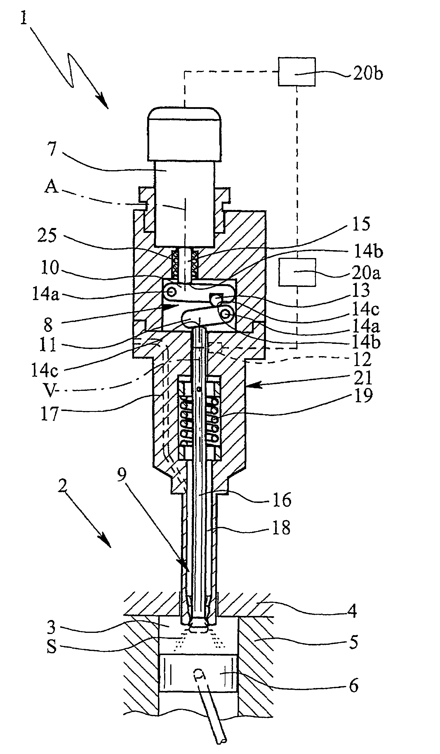
[0074]In the first embodiment, valve 9 is executed so that it opens outward, that is, towards combustion chamber 3.

[0075]In the illustrated embodiment, the fuel preferably is injected into combustion chamber 3 along a cone shape—in particular with an opening angle between 60° and 120°.

[0076]But if required, it is also possible to position a nozzle (not shown) with several passage openings at the end that projects into combustion chamber 3 in order to produce a corresponding number of fuel jets S that are directed in the desired directions.

[0077]Valve device 1 preferably comprises general housing 21, which can be a multi-part housing 21, as containment and / or mounting for integration of actuator 7, transmission device 8, valve 9, restoring device 19, the nozzle, sensor device 12, and / or signal processor 20a.

[0078]Further embodiments will be illustrated in the following with the help of FIGS. 2, 3, and 4. For simplification, sensor device 12, control device 20, and channel 17 are not...

second embodiment

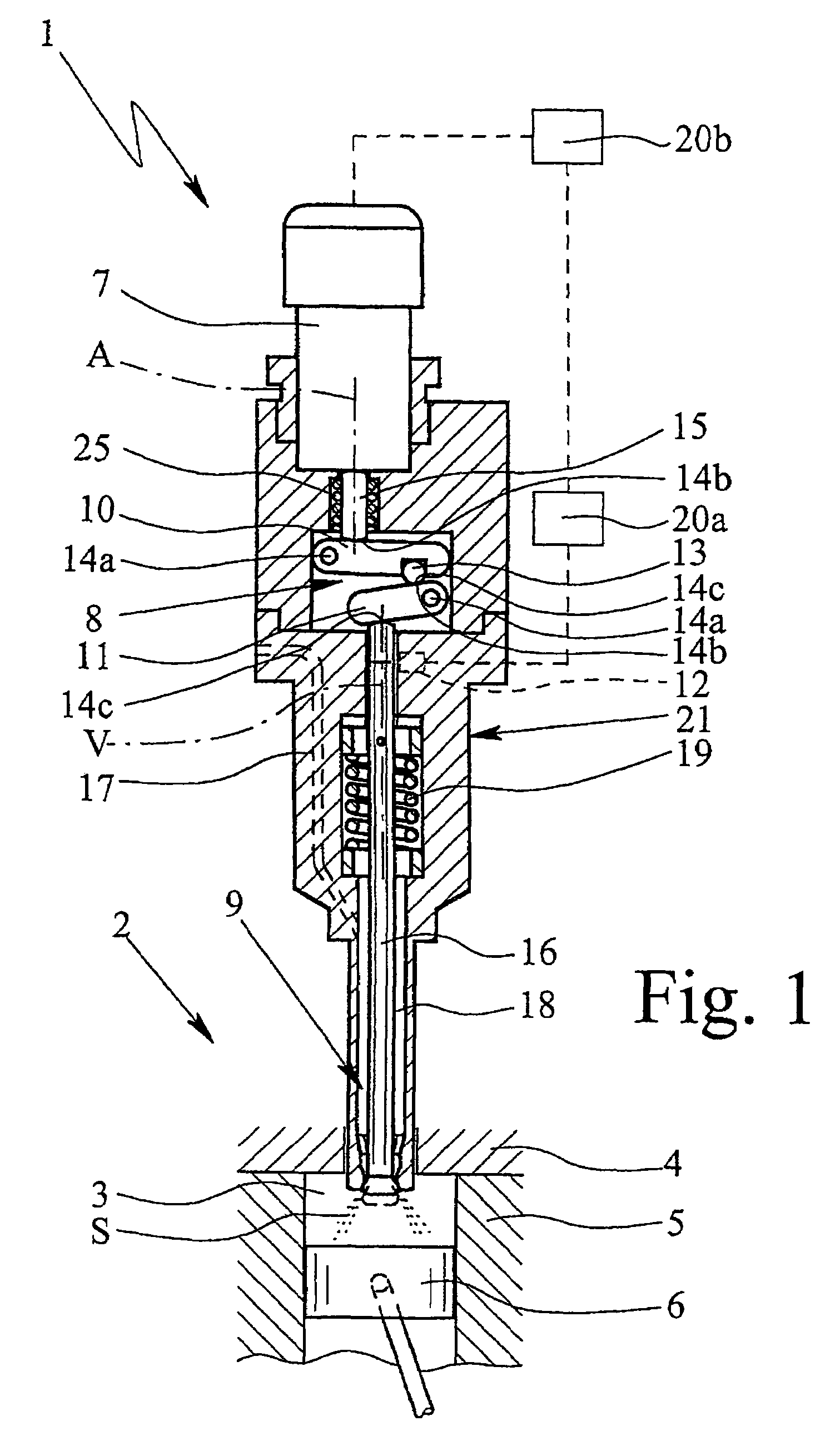
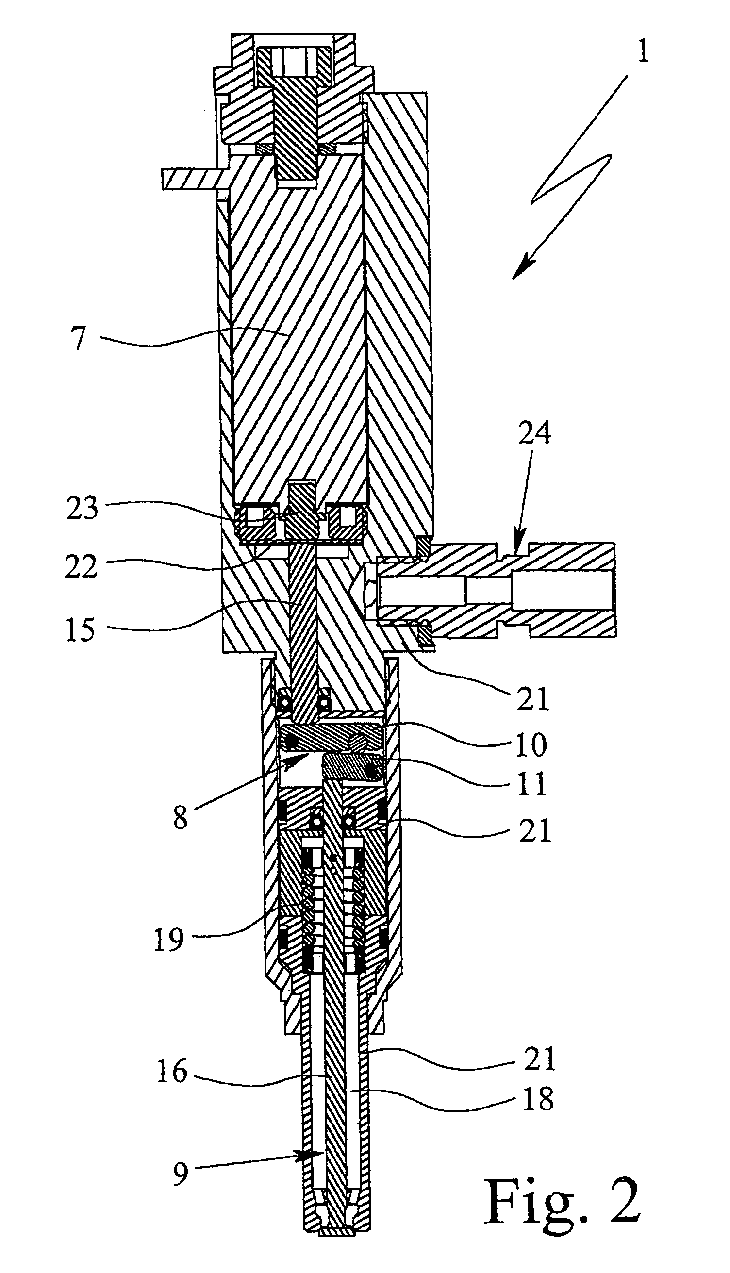
[0079]In valve device 1 shown in FIG. 2, actuator 7 is preferably enclosed and sealed gas-tight against transmission device 8, in particular by means of membrane 22. In the illustrated example, membrane 22 is installed or arranged between plunger 23 of actuator 7 and plunger 15 acting on transmission device 8.

[0080]According to the second embodiment, valve device 1 is equipped with lateral connection 24 to supply the fuel. Here as well, connection 24 communicates with interior space 18 of valve 9. As mentioned above, channel 17, as it is indicated in FIG. 1, is not shown.

[0081]FIG. 3 shows a sectional partial view of transmission device 8 of valve device 1 according to the second embodiment of FIG. 2. Transmission device 8 in this embodiment is fundamentally equivalent to the transmission device according to the first embodiment. FIG. 3 in particular illustrates the positions of support points 14a, contact points 14b, and output points 14c of levers 10 and 11.

[0082]Support points 14...

third embodiment

[0084]The schematic sectional view of FIG. 4 shows valve device 1. Here as well, lateral connection 24 for supplying the fuel is provided.

[0085]The third embodiment differs in important respects from the first and second embodiments. In the third embodiment, valve 9 is executed as an inward-opening needle valve and accordingly the transmission device is executed slightly different. Unlike the first and second embodiments, in the third embodiment, the direction of motion, that is, the direction of valve lift, of actuator 7 is directionally opposite from the resulting motion of valve 9 and valve element 16. This is achieved by positioning output point 14c of first lever 10, and thus input point 14b of second lever 11, on the outside of support point 14a of second lever 11; that is, support point 14a of second lever 11 is positioned between contact point 14b and output point 14c of second lever 11.

[0086]Upon activation of actuator 7, both levers 10, 11 swing in the same direction of ro...


PUM


Abstract

A valve device and a method directly inject gaseous fuel into a combustion chamber. A rapid response in a simple and compact design is achieved by a piezoelectric, magnetostrictive, or electromagnetic actuator that acts on a transmission device that comprises at least two levers, which are connected in series to increase the lift of the actuator to actuate a valve. An associated sensor device detects the position of a valve element, such that the actuator can be controlled to reduce the free play between the actuator and the valve.

Description

CROSS-REFERENCE TO RELATED APPLICATION(S)[0001]This application is a continuation-in-part of International Application No. PCT / EP2004 / 006130, having an international filing date of Jun. 7, 2004, entitled “Valve Device and Method for Injecting a Gaseous Fuel”. International Application No. PCT / EP2004 / 006130 claimed priority benefits, in turn, from German Patent Application No. 10326707.7 filed Jun. 11, 2003. International Application No. PCT / EP2004 / 006130 is also hereby incorporated by reference herein in its entirety.FIELD OF THE INVENTION[0002]The present invention relates to a valve device and a method for the direct and accurate injection of gaseous fuel into a combustion chamber, as well as the use of spring(s) and a position sensor in such a valve device to reduce free play between actuation elements.BACKGROUND OF THE INVENTION[0003]In the following paragraphs, prior art references pertaining to the subject matter of the application are set out.[0004]German Patent Publication N...

Claims


Application Information

Patent Timeline
Patent Type & Authority Patents(United States)
IPC IPC(8): F02B3/00B05B1/08F01L1/34F02M21/02F02M61/08F02M61/16F02M63/00F02M65/00
CPCF02M51/0603F02M61/08F02M61/161F02M65/005F02M21/0269F02M21/0263F02M21/0275F02M21/0254F02M2200/701Y02T10/32Y02T10/30
Inventor BARTUNEK, BERNDTOUCHETTE, ALAIN
Owner WESTPORT POWER
Why Eureka
Try Eureka